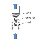
Ok, I think I might build a DIY flowmeter myself, so I'm putting more thought into how to make a practical prototype! Cones aren't easy, so here's an alternative attatched. It might look complex but I don't think it is really and should be buildable ...
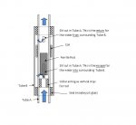
I'm thinking of using the pressure difference principle in the manometer example above, and having two connections off the main pipe (and the main pipe has a variation in bore diameter to create the pressure difference). This pressure difference creates a flow in a much smaller tube. This is Tube A in the diagram, which I'm even thinking could be a plastic drinking straw. Just thinking through how to make it ('Blue Peter' style!) ...
Construction
1. Get plastic straw and cut small slits as shown. The 'escape' slit should be nice and uniform if possible. The 'return' slit isn't critical and could be a hole, but must be positioned above maximum travel of rod.
2. At the bottom of the 'escape' slit insert and glue a suitable 'collar' into the straw. This just acts as a rest for the vertical rod when there isn't any flow so as long as it works it isn't critical.
3. Hopefully find a ferrite rod that can fit into the straw with minimal clearance. This might not be easy !! Maybe it just needs to be metal?? Might need to waterproof rod somehow to stop rust.
4. Wind coil. The whole priniciple of varying inductor is a bit of a guess. Makes sense that it will work best when the gap between rod and coil is small, so thin-walled TubeA and close fitting rod is best. Maybe magnet and hall effect sensor better ?? Cost??
5. Get another larger diameter TubeB that fits over TubeA. Not critical. The whole purpose of this is just to allow flow from the 'escape' to 'return' slits. Maybe just seal TubeB to TubeA with glue. The wires from the coil will have to come out somewhere, maybe through this glue.
6. Job done.
Operation - theory!
As flow rate increases, the rod lifts in the tube and changes the inductance of the coil. The water entering TubeA escapes through the 'escape' slit into TubeB, then returns through the 'return' slit back into TubeA.
As mentioned before, this variable inductor is part of an oscillator circuit and varies the frequency. The picaxe uses the Count command to measure the number of pulses per second. This method has natural inbuilt averaging.
@ DPG: you seem to know a bit about Hall effect sensors ...do you think it would be better to measure linear displacement using one? Are they fairly cheap??
")