DRPlayer with 08M2 chip

regpye

New Member
A while ago I wrote a small program for my wife and it has been working fine for that last couple of years.
It's purpose is to control the grey water coming from her washing machine. The water leaves the sink and goes to a tank that holds about 300L. This tank has a water pump connected to the mains power to move the water to some fruit trees in the backyard. To control that pump I wrote a picaxe program that is activated by 3 float switches that determine the level of the water, and turn on the pump as needed and off again when the tank is near emptied. It also has an alarm in case of something not working correctly and the tank over-fills due to a faulty pump, a clogged line or a faulty float switch.
While all of this is working perfectly I would like to use it as a learning exercise by adding on a DRPlayer to give some voice to the program.
I have changed the program slightly by changing the C.1 to be C.5 although I realise that is not ideal as C.5 is a serial pin and input only and really need to be disconnected when this program is in use. I did this because I need a pin to use to send to the DRPlayer.
I have ordered a few drplayers to play with but after ordering them and doing some research I found that I simply don't understand how to program for it.
The MP3 files I can make no problem and I understand the naming rules needed, but how to activate the code has me lost.
The code I am using at present is as follows;

Code:
#picaxe 08m2       ; Optional for verification
#no_data           ; Optional to speed downloading program modifications
setfreq m8        ; increase frequency
#terminal 9600

pause 2000         ; Recommended to give the terminal time to start up
; C.1 reserved for DRPlayer control
; C.4 Flashing RED LED
; C.0 Pump and BLUE LED, switches on a SSR to power the mains pump
; C.2 top float switch alarm activated if over full
; C.5 bottom float switch, maybe needs disconnecting
; C.3 middle float switch starts the pumping proccess
; GREEN LED connected across power pins with resistor shows power on

start:
Sertxd("Startup",13,10)
low C.0
low C.4
input 2         ;make pin 2 input
if pinC.2 = 1 then alarm ;top float switch

main:
Sertxd("Ready for filling, green LED on",13,10)

DO WHILE pinC.3 = 0
if pinC.2 = 1 then alarm ;top float switch   
LOOP

pump:
Sertxd("pumping, blue LED on, middle float on",13,10)
low C.4            ; turn of flashing red LED
DO WHILE pinC.3 = 1    ; middle float switch
high C.0              ; turn pump on, blue LED on
if pinC.2 = 1 then alarm ; top float switch, flashing red LED on
LOOP
DO WHILE pinC.5 = 1     ; bottom float switch, green LED on
LOOP

pump_off:

Sertxd("waiting for level to lower, bottom float on",13,10)
HIGH C.0
for b1 = 1 to 5 ; make a delay to empty tank more before turning off ?pump?
pause 1000
next b1
LOW C.0         ;switch pump off
Sertxd("pump_off, blue LED off, middle float off",13,10)
Sertxd("waiting for level to rise again",13,10)
goto main

alarm:
Sertxd("alarm, flashing red LED on, top float on",13,10)
HIGH C.0        ;switch pump on
HIGH C.4         ;turn on red LED indicator
for b1 = 1 to 2
pause 5000         ; wait a while
next b1
goto pump        ; check if still alarm state
 

hippy

Technical Support
Staff member
Having to move pins around when at capacity can be problematic and it seems that might be case here, needing an input on the Serial In pin.

One possibility is to add another PICAXE which monitors an output from what you already have and controls an MP3 player, klaxon or whatever. If one of your LED's is usually on or off you can issue a short pulse or serial byte which won't be observable but will be enough for the add-on to detect as an instruction to do whatever it does. This way little modification is required to the board and existing code.

As you are using C.0 to issue SERTXD reports as well as control the SSR and pump, you may be able to send unique text which can trigger MP3 playing, and also be able to see that being sent. That's probably the approach I would take.

For getting an MP3 player up and running, I would recommend embarking on a separate project to do that, get the program which plays the MP3 working standalone, then figure out how that should integrate with what you have.

Is your "DRPlayer" actually a typo for "DFPlayer", SPE033/SPE035, or something else ?

If it's that I would have expected existing and published code to have worked with that, that it was mostly a matter of wiring things up.

One option for an easy path might be the AXE171 PICAXE Audio Project Kit which can be used to get the MP3 parts working, and then it's a simple case of connecting to what you have to allow a triggering mechanism described earlier to start its playing.
 

regpye

New Member
s your "DRPlayer" actually a typo for "DFPlayer", SPE033/SPE035, or something else ?
Yes, Hippy, my mistake I should have written dfplayer.
The text output were only used for testing purposes and normally would be remmed out.
As they are the places we’re the MP3 files should play maybe the code could be modified to suit??
I don’t understand the coding method to call up the file, I understand the file must be a 001,mp3 etc and the directory 01
 

mikeyBoo

Senior Member
most mp3 players require 9600 baud & use the following format
The following is used on a 20M2 chip but will work on other Picaxe variants.
Note that hserout may be on different pins depending on Picaxe type.

The alias register stuff shown below lets me switch Picaxe flavors easily.
This allows building reusable code libraries.
X Y Z regs are primarily for passing arguments

Code:
; since remembering the 2 bytes comprising a word can be confusing (e.g. w2 is b4b5),
; it is easier to know what byte registers are part of what word registers as follows:
; e.g. pseudo-variable (i.e. alias) X can be any of w0...w13
;      albeit w0 & w1 are usually reserved as both are bit addressable
; XW = variable X word value, XL = lo-byte of variable X, XH = hi-byte of variable X
symbol XW = w2           ; alias register for w2 word value
symbol XL = b4           ; alias register for w2 lo-byte value
symbol XH = b5           ; alias register for w2 hi-byte value

symbol YW = w3           ; alias register for w3 word value
symbol YL = b6           ; alias register for w3 lo-byte value
symbol YH = b7           ; alias register for w3 hi-byte value

symbol ZW = w4           ; alias register for w4 word value
symbol ZL = b8           ; alias register for w4 lo-byte value
symbol ZH = b9           ; alias register for w4 hi-byte value


; mp3.command_Send --  (v1.00a by M. Ballew 07-03-2022)
;       send command & arguments to Catalex YX5300 MP3 Player
;       Catalex SD card is easy to configure on a PC as shown below
;       the default \MP3 & \ADVERT folders file names must start with 4 digits
;         (e.g. \MP3\0001.mp3  \ADVERT\0123.mp3)
;       It is possible to use longer file names (e.g. 0001.mp3 can be named 0001_barking dogs.mp3)
;         TAKE NOTE: \ADVERT files can be started while a \MP3 track is still playing
;                    e.g. a track from the \MP3 folder is started with command $12
;                         while track is still playing, an \ADVERT track is started with command $13.
;                         the \MP3 track will be suspended while the \ADVERT track plays
;                         Once the \ADVERT track completes, the \MP3 track will resume playing
;       NUMBERED folder names must start with 2 digits (01...99)
;                & file names must start with 3 digits (001...255)
;                (e.g. \01\001.wav  \02\222.mp3  \02\222_nagging female.mp3)
;       Command Examples:
;         XL = $01 : YW = $00  ; play next FAT file number
;         XL = $02 : YW = $00  ; play previous FAT file number
;         XL = $03 : YW = $01  ; play FAT file number 1 (valid FAT file numbers 1...255)
;         XL = $04 : YW = $01  ; Increase volume
;         XL = $05 : YW = $01  ; Decrease volume
;         XL = $06 : YW = $1E  ; set volume to 30 (any value 0...30)
;         XL = $07 : YW = $00  ; set EQ (0 Normal, 1 Pop, 2 Rock, 3 Jazz, 4 Classic, 5 Base)
;         XL = $08 : YW = $01  ; repeat play FAT file number 01 (valid 01...255)
;         XL = $09 : YW = $02  ; set file source (01 USB mem stick, 02 SD card, 03 Aux,
;                              ;     04 PC (debug mode), 05 Flash mem, 06 Sleep Mode
;         XL = $0A : YW = $00  ; Standby (aka Sleep) mode
;         XL = $0B : YW = $00  ; Normal mode (exit sleep mode)
;         XL = $0C : YW = $00  ; reset MP3 Player
;         XL = $0D : YW = $00  ; resume play (un-pause)
;         XL = $0E : YW = $00  ; pause play
;         XL = $0F : YH = $01 : YL = $02  ; Play folder 01 track 2 (folder 1...63, track 1...255)
;         XL = $10 : YW = $00  ; volume gain (0...31) ??
;         XL = $11 : YW = $00  ; Normal mode
;         XL = $11 : YW = $01  ; Repeat play (next track played will loop)
;         XL = $12 : YW = $01  ; play audio file 1 from default \MP3 folder (YW = track $1...$270F)
;         XL = $13 : YW = $01  ; play audio file 1 from default \ADVERT folder (YW = track $1...$270F)
;         XL = $14 : YH = $01  : YL = $02  ; play folder \01 track 01 (folder 01...15, track 001-999)
;         XL = $15 : YW = $00  ; stop playing \ADVERT track
;         XL = $16 : YW = $00  ; stop playing
;         XL = $17 : YW = $FF  ; Repeat play tracks in folder \255
;         XL = $18 : YW = $00  ; Random play all tracks
;         XL = $19 : YW = $00  ; loop currently playing track (YW = $01 stops looping)
;         XL = $1A : YW = $00  ; (YW = 00 cancel mute, 01 mute)
;         XL = $22 : YH = $1E : YL = $01  ; play first track $01 with volume = 30 ($1E)
;                                         ; i.e. play specified track at specified volume
; Status: (works ok)
;         haven't tried .wav files (kind of pointless)
;         currently the home control app always plays files from folder 01
;           (e.g. play related sound file in folder 01 (ZL = 1 plays track 1, etc.))
;
; Revisions:
;       none
;
; Arguments:
;       XL  command (in hex)
;       YH  argument hi-byte (in hex)
;       YL  argument lo-byte (in hex)
;       YW  (optionally load both YH & YL at once)
;
; Results:
;       send command to MP3 Player
;
; Example:
;       gosub mp3.command_Send  ; send command XL & args YW -> MP3 Player
;
mp3.command_Send:
    hserout 0,($7E, $FF, $06, XL, $00, YH, YL, $EF) ; send command to MP3 Player
    return
hope this helps...
 

hippy

Technical Support
Staff member
Yes, Hippy, my mistake I should have written dfplayer.
No problem; just that it's best to check we are on the same page, better to not go in one direction which may be entirely irrelevant.

I don’t understand the coding method to call up the file, I understand the file must be a 001,mp3 etc and the directory 01
It's been a while since I have done anything with MP3 but from the SPE035 datasheet - https://picaxe.com/docs/spe035.pdf - that states the files should be in an "MP3" directory on the card and filenames are 'four digits', so the first would be "0001.mp3". It also shows examples of code needed to control the DFPlayer.

If you first format the Card, then create a single (uppercase) "MP3" directory that will be the first directory so should work no matter how it is referenced. Your "0001.mp3" should be copied into that "MP3" directory.

There is also a more detailed third-party datasheet for the DFPlayer we have as - https://picaxe.com/docs/spe033.pdf

There should also be additional data on the forum from projects which have used the AXE171 or DFPlayer modules.

One problem with MP3 modules is that they can all use various chips, be subtly different even if similar, and datasheets are not always entirely clear in what they say, how files should be named and where they should be placed, how commands can be sent, whether checksums are mandatory or not.

The information in the SPE035 datasheet is correct, tried and tested by us, so would be considered definitive. It is however always possible that firmware within such modules may have changed over time but that would usually be adding things rather than changing them.
 

regpye

New Member
No problem; just that it's best to check we are on the same page, better to not go in one direction which may be entirely irrelevant.
I had been reading up on DRDOS and the DR must have stuck in my brain.
Thanks once again Hippy for you useful explanation, all will help me understand better.
I did do something with voice some years ago but it used a different method, different hardware, more expensive and hard to get SD cards as only some would work.
I think I still have a YouTube file that shows it in action.
 

regpye

New Member
There is also a more detailed third-party datasheet for the DFPlayer we have as - https://picaxe.com/docs/spe033.pdf
I have gone through all info I can find on this subject and now I am more confused than ever, I just don't understand what I have been reading.
I have determined that I will have to use C.0 to send the commands from as this is a 08M2 chip.
There will be only about four maybe five MP3 files in total and I will put them in a directory MP3,so the files would be 0001.MP3 . ..... 0005.MP3
I think I have to set the board rate and the frequency hsersetup B9600_16,%10 , but not sure if I have done that right or not.
As for sending the commands using hserout 0, ( think that is right for selecting C.0) but I am totally lost on how to send out the commands for individual MP3 files
 

AllyCat

Senior Member
Hi,
I have determined that I will have to use C.0 to send the commands from as this is a 08M2 chip.
No, AFAIK that is not true, although C.0 might indeed be the "best" pin to use.

I've not looked at the specific requirements recently, but it appears that the MP3 player needs to receive "RS232" commands at 9600 baud rate, and these will probably be "TTL" polarity (or "Idle High"), whilst PICaxe natively uses Idle Low at 4800 baud for the SERTXD command at 4 MHz clock.

The easiest way to transmit Idle-High at most baud rates is to use the SEROUT command which can use ANY Digital Output pin. Some references may indicate that SEROUT cannot be used on the SERTXD pin (i.e. C.0) but that is not correct, at least for the 08M2. For 9600 baud you will need to use at least SETFREQ M16 .

Alternatively, you could use HSEROUT on pin C.0 (only) with any clock frequency, or SERTXD on the same pin using SETFREQ M8 (for 9600 baud) with an external hardware inverter (e.g. an NPN transistor) if Idle-High is required.

Cheers, Alan.
 

kfjl

Member
Code:
; Picaxe 20X2 Programme to control a DFPlayer Mini MP3 player using a Sony-type telly remote.

#picaxe 20x2
#no_table
#no_data

Symbol TX = B.4
Symbol RX = C.3
Symbol BAUD_FREQ = M8
Symbol BAUD = T9600_8
Symbol cmd = b0
Symbol arg = w1 ; b3:b2
Symbol arg.lsb = b2
Symbol arg.msb = b3
Symbol IRpin = C.6
Symbol infra = b13

init:

cmd = $07:arg = $01: Gosub Send                ; Mode "Normal"
pause 500
cmd = $09 : arg = $0002 : Gosub Send            ; Specify playback source as SD card
Pause 500

main:

irin IRpin,infra
sertxd(#infra,CR,LF)

if infra >= 0 AND infra<9 then                 ; If a number key (1-9) was pressed
    cmd = $03 : arg = infra+1 : Gosub Send        ; Start playing that track
endif

if infra = 18 then                        ; Right arrow
    cmd = $01: Gosub Send                ; Play next track
    pause 500
endif

if infra = 19 then                        ; Left arrow
    cmd = $02: Gosub Send                ; Play previous track
    pause 500
endif
    
if infra = 16 then                        ; Up arrow
    cmd = $04: Gosub Send                ; Increase volume
endif

if infra = 17 then                        ; Down arrow
    cmd = $05: Gosub Send                ; Decrease volume
endif

if infra = 9 then
    cmd = $0E: Gosub Send                ; Standby (stop sound)
    pause 100
    cmd = $0B: Gosub Send                ; Normal working (re-arm)
    pause 100
endif
        
goto main

Send:
    SerOut TX, BAUD, ( $7E, $FF, $06, cmd, $00, arg.msb, arg.lsb, $EF )
Return
Here's what's on the SD card in the video:
0001_Fox.mp3
0002_WB_Cartoon1.mp3
0003_Thin_Lizzy_Whiskey_In_The_Jar.mp3
0004_Kansas_Dust_In_The_Wind.mp3
0005_Light_Flight.mp3
0006_Land_Of_Confusion.mp3
0007_Sinfonia_To_Cantata_No_29.MP3

MP3-player
 

AllyCat

Senior Member
Hi,

Just a slight correction to my previous post and a few tips about kfjl's code: For 9600 baud, the minimum clock frequency is 8 MHz, which is the default clock frequency of the X2 chips. So to convert the program to an M2 chip (which has a default of 4 MHz) needs the addition of a SETFREQ M8 command. The Symbol TX =... can be set to any available output pin, i.e. C.0 to C.2 and C.4 on the 08M2. The if infra =... sections of the program detect various remote Control commands, which can be replaced by just an appropriate setting of the cmd and arg variables and then a Gosub Send .

Complete operation of the MP3 player can be validated by receiving replies on the RX pin, but the program doesn't appear to actually use that feature, and with an 08M2 it could be quite difficult to find a "spare" pin. Strictly, the 08M2 has only 3 "General Purpose" I/O pins (C.1, C.2 and C.4) but there are various "tricks" that can pack more functions onto the chip. Pins C.3 and C.5 are "Input Only" and personally I try to avoid using the serial / programming pin C.5 at all, because it can require the use of the RECONNECT command or the "Hard Reset" procedure, which can be a problem, particularly for novice users. Thus, I might reserve C.5 for (only) the RX function.

The listing in #1 reserves three pins for Switch inputs and two outputs for LEDs. However, it's quite easy to input the state of all 3 switches on one pin by making it an an analogue input, for example by connecting 10k , 20k and 40k resistors (one in series with each switch), to mix the voltage onto a single pin. That can potentially generate 8 different voltage levels, but if they are measuring the same water level then only 4 values are likely (the other 4 might conveniently indicate a fault condition). Similarly, two LEDs can be driven from a single Output pin, one wired to be Active High and the Other Active Low. Both could be lit by using a 50% PWM Output on C.2 (or both Off with an Input Command), but generally I prefer to put LEDs on the "Serial Programming" pins C.0 and C.5, rather than a motor, etc., because they are not "upset" by the pulses present during the programming process.

Another useful feature is the "Weak Pullup Resistors" (~ 35 kohms) which are available on ALL of the 08M2's Input and Output pins. This might be sufficient to (weakly) light a LED on an "input" pin, or to drive a Logic Level FET. Another possibility is to detect a "Tri-State" switched level (Low, High and Weak Pull-Down) on a single Digital-only Input pin, by switching on and off the internal WPU resistor (and testing if the 0/1 digital level changes). But even without these resistors, you could potentially put the LEDs, Switches, Pump Motor and MP3 player (TX) on the four Output-capable pins, then RX optionally on C.3, with no need to even involve C.5.

Cheers, Alan.
 

regpye

New Member
I think I am starting to understand a bit better now, can't wait for the DFPlayers to arrive so I can test it out.
I have made some test files and saved to a FAT formatted SD card ready to test.
Thanks guys for all your inputs, any more would be welcome as I am still trying to learn as much as I can, the old brain is not as agile as it used to be, the problem of getting old.
 

hippy

Technical Support
Staff member
One additional tip - As noted in the SPE035 datasheet, Blockly has built-in commands for operating the DFPlayer. That means you can create skeleton code in Blockly, then use the PICAXE Basic conversion of that in other projects. You can also use it 'a command at a time' to see what Basic commands are used for a particular function.
 

1968neil

Senior Member
Just a quick thought.......
The DF player will require two pins.
I find using the BUSY pin is a must if you want the operation to be reliable.

I have used 100's of these modules in props and interfaces over the past few years and they are very good and very useful.
If you use mp3 files to announce the condition you could possibly do away with the LED's..... and maybe the SERTXD.

Or free up the inputs by using an a single ADC channel to read the switches if they switch in a resistor and read them as a R2R ladder
 

1968neil

Senior Member
Code:
Symbol Busy_Pin = PinC.1 
Symbol Busy_Delay = 100

Check_Busy:
Do
pause Busy_Delay
loop while Busy_Pin=0
Return
Whilst the sound file is playing the busy pin goes low, If another command to play a different file is sent it would allow the previous file to finish first.
This makes the use of sound much more user friendly.
I use them as voice annunciators modules in many commercial applications.
If i get a few mins later this evening i will post an example of how it would work in your application, this may help you understand the format, which is very confusing at first.
I got the answers i needed i fair while ago from this forum via the ever knowledgeable Hippy ! ;)
 

regpye

New Member
Whilst the sound file is playing the busy pin goes low, If another command to play a different file is sent it would allow the previous file to finish first.
That is a very good and clear explanation, thanks a lot for that.
I got the answers i needed i fair while ago from this forum via the ever knowledgeable Hippy !
Yes you are right, I think the forum would be lost without Hippy, he sure knows a lot I have found, a great asset to us all.
 

1968neil

Senior Member
Code:
Symbol Busy_Pin = PinC.1
Symbol Busy_Delay = 200
Symbol TX = B.4
Symbol BAUD_FREQ = M8
Symbol BAUD = T9600_8

Symbol cmd = b0
Symbol arg = w1 ; b3:b2
Symbol arg.lsb = b2
Symbol arg.msb = b3

Main:
 if pinC.2 = 1 then Gosub alarm ;top float switch
Goto Main

alarm:

High TX ; set TX pin high for idle high serial
Pause 500
SerTxd("Play MP3 folder song 0001.mp3", CR, LF )
cmd = $12 : arg = 0001 : Gosub Send    ;$12 play tracks from the default \MP3 folder - 0001 = track 1
Pause 500
Return


Send:
 SetFreq BAUD_FREQ
 Pause 10
 SerOut TX, BAUD, ( $7E, $FF, $06, cmd, $00, arg.msb, arg.lsb, $EF )
 gosub Check_Busy
 SetFreq MDEFAULT
 Return
 

Check_Busy:
Do
pause Busy_Delay
loop while Busy_Pin=0
Return
 

regpye

New Member
Code:
Symbol Busy_Pin = PinC.1
Symbol Busy_Delay = 200
Symbol TX = B.4
Symbol BAUD_FREQ = M8
Symbol BAUD = T9600_8

Symbol cmd = b0
Symbol arg = w1 ; b3:b2
Symbol arg.lsb = b2
Symbol arg.msb = b3

Main:
if pinC.2 = 1 then Gosub alarm ;top float switch
Goto Main

alarm:

High TX ; set TX pin high for idle high serial
Pause 500
SerTxd("Play MP3 folder song 0001.mp3", CR, LF )
cmd = $12 : arg = 0001 : Gosub Send    ;$12 play tracks from the default \MP3 folder - 0001 = track 1
Pause 500
Return


Send:
SetFreq BAUD_FREQ
Pause 10
SerOut TX, BAUD, ( $7E, $FF, $06, cmd, $00, arg.msb, arg.lsb, $EF )
gosub Check_Busy
SetFreq MDEFAULT
Return


Check_Busy:
Do
pause Busy_Delay
loop while Busy_Pin=0
Return
Wow that was quick, I can't wait for the DFPlayers to arrive so I can try this out.
This has saved me a lot of wasted time and I can understand now how it should work., the documents are very confusing for me, not having done this type of coding before.
Thanks so much for your input.
I will be using 20M2 chips for later projects, I just got some and also 14M2 and several more 08M2 chips, I have a few 18M2 as well, but they are a bit odd as the pins are arranged differently.
I am guessing that this code will work on all these chips with changes to pins etc?
 

1968neil

Senior Member
Wow that was quick, I can't wait for the DFPlayers to arrive so I can try this out.
This has saved me a lot of wasted time and I can understand now how it should work., the documents are very confusing for me, not having done this type of coding before.
Thanks so much for your input.
I will be using 20M2 chips for later projects, I just got some and also 14M2 and several more 08M2 chips, I have a few 18M2 as well, but they are a bit odd as the pins are arranged differently.
I am guessing that this code will work on all these chips with changes to pins etc?
Yes all should be scalable to the larger PICAXE's
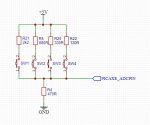
Further to my previous post, i have attached a circuit that allows you to use 1 ADC channel with Four switch inputs that some may find useful when you run out of Pins :)
Regards
Neil

25835
 

regpye

New Member
Further to my previous post, i have attached a circuit that allows you to use 1 ADC channel with Four switch inputs that some may find useful when you run out of Pins
Thanks for that Neil, yes it will be very useful.
I was only wondering yesterday about something very similar and how I could make a ladder up and then use PE6 to read the values and report back so I could determine what settings to use in code for the various resistor values.
I got the idea after using an LDR and figured that I could use fixed resistors to replace it and then have fixed values to select from.
 

Jeff Haas

Senior Member
That solution is also discussed in this thread, using a rotary switch:

It works well!
 

regpye

New Member
Yes all should be scalable to the larger PICAXE's
Further to my previous post, i have attached a circuit that allows you to use 1 ADC channel with Four switch inputs that some may find useful when you run out of Pins :)
Regards
Neil

View attachment 25835
I got an idea for our local history group,.
They have a lot of photos that could have a button to press and a description is spoken about the photo. This would make a simple display become more alive.
I am not sure if it would be possible to have say 20 or so photos on a big panel with a button on each that when pressed would play the appropriate file for that photo.
Making it so only one could play at a time would be important or kids could be pressing all the buttons at one time.
Just a thought, but I reckon it would make a good project.
 

1968neil

Senior Member
I did a similar project for a local museum a while back.
They had a mock up of a wartime building and as you opened the little doors it triggered the sound file with effects and a snippet of speech from news clips of the time. worked very well.
So your idea is totally do-able.
 

hippy

Technical Support
Staff member
I am not sure if it would be possible to have say 20 or so photos on a big panel with a button on each that when pressed would play the appropriate file for that photo.
Totally do-able as 1968neil says. I would say it falls into the category of "what a PICAXE is perfect for".

You can have a 5 x 4 button matrix or larger which is easy enough with the right PICAXE and you could even hack a PS/2 keyboard. Then you just need to scan for a button push or wait for a key press, play the track and ignore any new pushes until it has finished.

If it's a button matrix I believe that can also be used to light a LED in the button or next to it so it's more obvious which the track is for. It's a slightly more complicated matrix but might well be worth the effort.
 

regpye

New Member
Totally do-able as 1968neil says. I would say it falls into the category of "what a PICAXE is perfect for".

You can have a 5 x 4 button matrix or larger which is easy enough with the right PICAXE and you could even hack a PS/2 keyboard. Then you just need to scan for a button push or wait for a key press, play the track and ignore any new pushes until it has finished.

If it's a button matrix I believe that can also be used to light a LED in the button or next to it so it's more obvious which the track is for. It's a slightly more complicated matrix but might well be worth the effort.
I cobbled this together with what Neil has shown me. I am still waiting on the DFPlayers to arrive, so I could only test it in the simulator.
Need to slide the ADCs back to zero between button pushes to simulate a momentary button press. Seems to work okay.
I am using two ADCs with a ladder on each of four switches, I think I could increase the number to maybe double that

Code:
main:
Symbol Busy_Pin = PinC.3
Symbol Busy_Delay = 200
Symbol TX = c.4
Symbol BAUD_FREQ = M8
Symbol BAUD = T9600_8

Symbol cmd = b0
Symbol arg = w1 ; b3:b2
Symbol arg.lsb = b2
Symbol arg.msb = b3


b10 = 0           ; initialize b10 variable
b11= 0        ; initialize b11 variable

readadc C.1,b10     ; read adc variable into b10
if b10 >10 and b10 < 40 then one
if b10 > 40 and b10 < 80 then two
if b10 > 80 and b10 < 120 then three
if b10 > 120 then four
readadc C.2,b11     ; read adc variable into b10
if b11 >10 and b11 < 40 then five
if b11 > 40 and b11 < 80 then six
if b11 > 80 and b11 < 120 then seven
if b11 > 120 then eight

goto main
one:
High TX ; set TX pin high for idle high serial
Pause 500
SerTxd("Play MP3 folder song 0001.mp3", CR, LF )
cmd = $12 : arg = 0001 : Gosub Send    ;$12 play tracks from the default \MP3 folder - 0001 = track 1
wait 2

goto main

two:
High TX ; set TX pin high for idle high serial
Pause 500
SerTxd("Play MP3 folder song 0002.mp3", CR, LF )
cmd = $12 : arg = 0002 : Gosub Send    ;$12 play tracks from the default \MP3 folder - 0002 = track 1
wait 2

goto main

three:
High TX ; set TX pin high for idle high serial
Pause 500
SerTxd("Play MP3 folder song 0003.mp3", CR, LF )
cmd = $12 : arg = 0003 : Gosub Send    ;$12 play tracks from the default \MP3 folder - 0003 = track 1
wait 2
goto main

four:
High TX ; set TX pin high for idle high serial
Pause 500
SerTxd("Play MP3 folder song 0004.mp3", CR, LF )
cmd = $12 : arg = 0004 : Gosub Send    ;$12 play tracks from the default \MP3 folder - 0004 = track 1
wait 2
goto main

five:
High TX ; set TX pin high for idle high serial
Pause 500
SerTxd("Play MP3 folder song 0005.mp3", CR, LF )
cmd = $12 : arg = 0005 : Gosub Send    ;$12 play tracks from the default \MP3 folder - 0005 = track 1
wait 2
goto main

six:
High TX ; set TX pin high for idle high serial
Pause 500
SerTxd("Play MP3 folder song 0006.mp3", CR, LF )
cmd = $12 : arg = 0006 : Gosub Send    ;$12 play tracks from the default \MP3 folder - 0006 = track 1
wait 2
goto main

seven:
High TX ; set TX pin high for idle high serial
Pause 500
SerTxd("Play MP3 folder song 0007.mp3", CR, LF )
cmd = $12 : arg = 0007 : Gosub Send    ;$12 play tracks from the default \MP3 folder - 0007 = track 1
wait 2
goto main

eight:
High TX ; set TX pin high for idle high serial
Pause 500
SerTxd("Play MP3 folder song 0008.mp3", CR, LF )
cmd = $12 : arg = 0008 : Gosub Send    ;$12 play tracks from the default \MP3 folder - 0008 = track 1
wait 2
goto main


Send:
 SetFreq BAUD_FREQ
 Pause 10
 SerOut TX, BAUD, ( $7E, $FF, $06, cmd, $00, arg.msb, arg.lsb, $EF )
 gosub Check_Busy
 SetFreq MDEFAULT
 Return
 

Check_Busy:
Do
pause Busy_Delay
loop while Busy_Pin=0
Return
 

eclectic

Moderator
if b10 >10 and b10 < 40 then one
if b10 > 40 and b10 < 80 then two
if b10 > 80 and b10 < 120 then three
if b10 > 120 then four

What happens when b10 = 40 or 60 or 80 or 100?
 

regpye

New Member
if b10 >10 and b10 < 40 then one
if b10 > 40 and b10 < 80 then two
if b10 > 80 and b10 < 120 then three
if b10 > 120 then four

What happens when b10 = 40 or 60 or 80 or 100?
Good question, I am only learning, and I am sure there will be a much better way to do it properly.
 

hippy

Technical Support
Staff member
For decoding a set of values in a range I prefer a SELECT-CASE to avoid errors of missed values and to save on typing -
Code:
Select Case b10
  Case > 120 : Goto four
  Case >  80 : Goto three
  Case >  40 : Goto two
  Case >  10 : Goto one
End Select
You can use "<", "<=" or ">=" as preference takes you.

One thing I would recommend is to get familiar with using named variables. Choose a meaningful name such as 'button_adc' and then use 'symbol button_adc = b10' to actually allocate it to a 'b' variable. That can make code a whole lot more readable and understandable. 'Select Case button_adc' will save people, including yourself at a later date, having to determine what 'b10' is actually used for. It will also help avoid accidentally reusing a 'b' or 'w' variable by mistake as code grows.

Where you have -
Code:
one:
High TX ; set TX pin high for idle high serial
Pause 500
SerTxd("Play MP3 folder song 0001.mp3", CR, LF )
cmd = $12 : arg = 0001 : Gosub Send    ;$12 play tracks from the default \MP3 folder - 0001 = track 1
wait 2
goto main
You can change 'one' and all the rest to use a single routine which will save code space -
Code:
one:
  arg = 1 : Goto playtrack
two:
  arg = 2 : Goto Playtrack

playtrack:
  High TX ; set TX pin high for idle high serial
  Pause 500
  BinToAscii arg, dig5,dig4,dig3,dig2,dig1
  SerTxd("Play MP3 folder song ", #dig4, #dig3, #dig2, #dig1, ".mp3", CR, LF )
  cmd = $12 : Gosub Send    ;$12 play tracks from the default \MP3 folder - 0001 = track 1
  wait 2
  goto main
 

regpye

New Member
if b10 >10 and b10 < 40 then one
if b10 > 40 and b10 < 80 then two
if b10 > 80 and b10 < 120 then three
if b10 > 120 then four

What happens when b10 = 40 or 60 or 80 or 100?
I had to get up out of bed because I couldn't sleep thinking about this question.
I have come to the conclusion that this problem could never happen because the resistors are a fixed value and the ADC ranges would be selected with the resistor value somewhere to the middle of either extreme..
Think about that.
 

regpye

New Member
For decoding a set of values in a range I prefer a SELECT-CASE to avoid errors of missed values and to save on typing -
Code:
Select Case b10
  Case > 120 : Goto four
  Case >  80 : Goto three
  Case >  40 : Goto two
  Case >  10 : Goto one
End Select
You can use "<", "<=" or ">=" as preference takes you.

One thing I would recommend is to get familiar with using named variables. Choose a meaningful name such as 'button_adc' and then use 'symbol button_adc = b10' to actually allocate it to a 'b' variable. That can make code a whole lot more readable and understandable. 'Select Case button_adc' will save people, including yourself at a later date, having to determine what 'b10' is actually used for. It will also help avoid accidentally reusing a 'b' or 'w' variable by mistake as code grows.

Where you have -
Code:
one:
High TX ; set TX pin high for idle high serial
Pause 500
SerTxd("Play MP3 folder song 0001.mp3", CR, LF )
cmd = $12 : arg = 0001 : Gosub Send    ;$12 play tracks from the default \MP3 folder - 0001 = track 1
wait 2
goto main
You can change 'one' and all the rest to use a single routine which will save code space -
Code:
one:
  arg = 1 : Goto playtrack
two:
  arg = 2 : Goto Playtrack

playtrack:
  High TX ; set TX pin high for idle high serial
  Pause 500
  BinToAscii arg, dig5,dig4,dig3,dig2,dig1
  SerTxd("Play MP3 folder song ", #dig4, #dig3, #dig2, #dig1, ".mp3", CR, LF )
  cmd = $12 : Gosub Send    ;$12 play tracks from the default \MP3 folder - 0001 = track 1
  wait 2
  goto main
Once again Hippy, you have produced some good advise and information, I will try and keep that in mind and also try to implement them in future coding. I will check it out more fully in daylight, it is the middle of the night here in Australia now. Thanks once again.
 

regpye

New Member
It is now 5 am and I have had a broken sleep all night thinking about this interesting subject (interesting to me at least)
In theory the ADC values that I have selected have only been a guess in order to test the theory out, which it does in a controlled simulation. (still waiting on the hardware to arrive, so no real test yet)
In practice it will be way out because of the settings of the ADC ranges that I have used
.
My question now is, what would be the best way to set a working range of a resistor ladder in either resistances or ADC ranges?
Neil has given an example circuit with some resistor values but no explanation on the ADC settings for each resistor, so I am guessing that if four resistors are used and the total range is from 0-255 ADC it would be a matter of dividing that range up into four equal parts maybe. An LDR is not a linear devise and would be different, but using fixed value resistors gives more control of accuracy.
There must be a way of determining these values rather than a hit or miss approach like I have done.
 

1968neil

Senior Member
If you make up the little circuit I posted in post #21.

connect it to an ADC pin and program the chip with
Code:
Symbol Res_Ladder1= C.1
Symbol Ladder_Value = b0

Main:
readadc Res_Ladder1,Ladder_Value ; read ADC Pin into Ladder Value  (variable b0)

sertxd("The value of ADC is",#Ladder_Value,13,10)  ; transmit to computer
pause 200 ; short delay
goto main ; loop back to start
Then run it and after you press each switch make a note of its value from the serial window that pops up.
Then using the Select Case scenario that Hippy has suggested you can put the known values in.
You can use a > or < than to give your values a few degrees either way of hysteresis.

I'd also agree with Hippy on using the Symbols to alias the variables and Pin numbers this makes the code mush easier to read and find errors.
It's also vary handy when you need to change a pin for another as you won't have to trawl through lines of code to find every instance of "b0 or b1" you simple just change it in the symbol definitions at the beginning of your listing.

You'll find the values of resistor in the circuit I posted will give you enough span for each switch to have its own "Space" in the results.
I would also suggest adding a small capacitor (100n will do) between the ADC pin and ground to keep any reading as noise free as possible.
This is common good practice.
Enjoy :)
 

regpye

New Member
If you make up the little circuit I posted in post #21.

connect it to an ADC pin and program the chip with
Code:
Symbol Res_Ladder1= C.1
Symbol Ladder_Value = b0

Main:
readadc Res_Ladder1,Ladder_Value ; read ADC Pin into Ladder Value  (variable b0)

sertxd("The value of ADC is",#Ladder_Value,13,10)  ; transmit to computer
pause 200 ; short delay
goto main ; loop back to start
Then run it and after you press each switch make a note of its value from the serial window that pops up.
Then using the Select Case scenario that Hippy has suggested you can put the known values in.
You can use a > or < than to give your values a few degrees either way of hysteresis.

I'd also agree with Hippy on using the Symbols to alias the variables and Pin numbers this makes the code mush easier to read and find errors.
It's also vary handy when you need to change a pin for another as you won't have to trawl through lines of code to find every instance of "b0 or b1" you simple just change it in the symbol definitions at the beginning of your listing.

You'll find the values of resistor in the circuit I posted will give you enough span for each switch to have its own "Space" in the results.
I would also suggest adding a small capacitor (100n will do) between the ADC pin and ground to keep any reading as noise free as possible.
This is common good practice.
Enjoy :)
Thanks Neil for the further explanation, it is clearer now. I was thinking about using a small cap to stop possible button bounce or noise as in other projects I found it was needed too.
Lots to learn and try out, I guess I have got the bug now.
 

AllyCat

Senior Member
Hi,
There must be a way of determining these values rather than a hit or miss approach like I have done.
The circuit topology can determine how a selector switch array behaves if two (or more) switches are pressed at the same time. For example it's possible for one of the activated switches to have "priority" and still be identified, even if others are also operated. An example of this is a chain of (equal) resistors between supply and ground, with each switch connecting its associated tap to Earth (or the supply); once a switch is activated, any switches lower down the chain will be ignored (because all those taps will already be at zero volts). Alternatively, each switch can be given a different "weight" such that it's possible to detect if two (or more) switches have been activated, and possibly identify each of them. READADC10 can be used to indicate one of 1024 levels, which then can be rounded to the nearest of 256 levels with perfect accuracy. Thus the detection of one in 256 switches is technically possible, or with binary weighted switches, any combination of 8 switches can be identified.

Also it depends on the type of switches, which can be Open/Closed, or Change-over type (e.g. a Logic level, such as the BUSY signal from the player above). Generally, the Open/Closed can be considered as a Current switch (zero if open) whilst the Changeover is a Voltage switch. Since the ADC is a voltage detector, the design and calculations will usually be easier with Logic levels than Open/Closed switches. Typically, current switches will lead to Logarithmic characteristics and Voltage switches to Linear scales. But traditionally a "Ladder" network has a pair of resistors (with values of R and 2R) for each (Voltage) switch, which acts as an attenuator to give accurate binary weighting of its inputs (e.g. for a DAC or ADC). A LDR will typically have a logarithmic range from say 100 ohms to 1M with a "middle" value of 10k, whilst a (linear) 100k potentiometer will normally have a middle value around 50k (as would a string of equally-valued resistors).

Resistors are normally supplied in a series of "Preferred" values (with decade multipliers), for example 10 , 12 , 15 , 18 , 22 , 27 , 33 , 39 , 47 ,56 , 68 , 82 , (100) for the E12 series. Those aren't arbitrary values, each value is about 20% larger than the previous; the E24 series uses 10% steps to fill in all the gaps ( 11 , 13 , 16 , 20 , etc.), with the E6 and E3 omitting values for less accurate components such as (electrolytic) capacitors. Values chosen (with equal spacing) from one of these series will often be appropriate to use with open/closed type switches, with the total range dependent on the ADC resolution.

Cheers, Alan.
 

1968neil

Senior Member
This should give anyone a good head start, the code reads the SD card and reports back how many tracks are stored on it.
It then used the ADC channel to read the Switches as posted earlier, it allows for slight variations in the adc value on a switch read.
Then it should play a file from the sd card dependant on the switch pressed.
You could also add your own control code for relays in the the Play : routines if you like.
There are more elegant ways of writing the code im sure, i am by no means a programmer ! , however this should get you going using the methods previously described.
Have fun !
Regards Neil


Code:
'****************************************************************************************
;*            Picaxe DF Player with ADC switch inputs DEMO                              *
;****************************************************************************************
 ;#PICAXE-14M2

;****************************************************************************************
;*                                I/O DEFINITIONS                                       *
;****************************************************************************************
Symbol BUSY_PIN          = pinB.5  ' Busy Output from MP3 Module
Symbol Switches1         = B.1     ; Switch stack ADC1 input
Symbol Switches2         = B.2     ; Switch stack ADC2 input
;****************************************************************************************
;*                              SERIAL DEFINITIONS                                      *
;****************************************************************************************
Symbol TX               = B.4     'Serial Output to MP3 Module
Symbol RX               = B.3     'Serial Input from MP3 Module
Symbol BAUD_FREQ        = M8      'Baud Rate Setting from MP3 Module
Symbol BAUD             = T9600_8 'Baud Rate for serial monitor to pc
;****************************************************************************************
;*                             VARIABLE DEFINITIONS                                     *
;****************************************************************************************
Symbol cmd              = b0      ' Command Byte Variable
Symbol arg              = w1      ; b3:b2        ' 16 bit variable
Symbol arg.lsb          = b2      ' Least significant bit variable
Symbol arg.msb          = b3      ' Most significant bit variable
Symbol Busy_Delay       = 150     ' Sets 150us delay to check Busy input
Symbol Switch_Result1   = b4      ' Variable to store siwtch stack value
Symbol Switch_Result2   = b5      ' Variable to store siwtch stack value
;***************************************************************************************
;*                              COMMAND DEFINITIONS                                     *
;****************************************************************************************
Symbol Volume           = $06     ' Hex Command to set Volume of DF Player Module
Symbol MP3              = $12     ' Hex Command to Select MP3 File Folder on SD Card
Symbol Advert           = $13     ' Hex Command to Select Advert File Folder on SD Card

;*****************************************************************************************
;              READ NUMBER OF FILES ON SD CARD Or USB THUMBDRIVE                        *
;*****************************************************************************************

cmd = $48                         ; $48 Reads SD Card $47 reads External USB Stick Drive
Gosub SendAndReceiveReply
SerTxd( "Tracks=", #arg, CR, LF )
;------------------------------------------------------------------------------------------
Start:
      High TX                  ' set TX pin high for idle high serial
      Pause 1000
      ;cmd = Volume : arg = 15 : Gosub Send    ; Set volume to 15
      Pause 1000
        
MAIN:
     Pause 500       
     Gosub Read_Switches
Goto main                       'loop back to main

Read_Switches:

ReadADC Switches1,Switch_Result1
if Switch_Result1 > 128 then gosub Switch_Pressed
Return

Switch_Pressed:

If switch_Result1 >120 or switch_Result1 <130 then Play1  ; if value of switch pressed is between 120 and 130 then play file 1
If switch_Result1 >131 or switch_Result1 <140 then Play2
If switch_Result1 >141 or switch_Result1 <150 then Play3
If switch_Result1 >151 or switch_Result1 <160 then Play4

Return

Play1:     
    cmd = Mp3 : arg = 0001 : Gosub Send         'Play Sound File 0001
    gosub Send
Play2:     
    cmd = Mp3 : arg = 0002 : Gosub Send         'Play Sound File 0002
    gosub Send
    
Play3:     
    cmd = Mp3 : arg = 0003 : Gosub Send         'Play Sound File 0003
    gosub Send
    
Play4:     
    cmd = Mp3 : arg = 0004 : Gosub Send         'Play Sound File 0004
    gosub Send   
    
Send:

     SetFreq BAUD_FREQ                                                     ; Set Baud Freq for MP3 player
     Pause 10                                                              ;wait 10us
     SerOut TX, BAUD, ( $7E, $FF, $06, cmd, $00, arg.msb, arg.lsb, $EF )   'Send Command to play file from the SD Card
     Gosub Check_Busy                                                      'check if busy
     SetFreq MDEFAULT                                                      ' Reset baud rate back to normal
     Return

Check_Busy:
 Do                             ; Sit in this Do loop until Busy pin = 1
 pause Busy_Delay
 loop while Busy_Pin=0
 Return   
    
SendAndReceiveReply:
  SetFreq BAUD_FREQ                                                       ; Set Baud Freq for MP3 player
  Pause 10                                                                ; wait 10us
  SerOut TX, BAUD, ( $7E, $FF, $06, cmd, $00, arg.msb, arg.lsb, $EF )     ; Send Command to ask for the data from the SD card
  SerIn  RX, BAUD,   arg, arg, arg, arg, arg, arg.msb, arg.lsb            ; Receive data into variables
  SetFreq MDEFAULT                                                        ; reset baud rate back to default
  Return
 

mikeyBoo

Senior Member
The following code can be downloaded to your Picaxe chip to quickly test your mp3 player
make a directory called 01 on your SD card
make mp3 tracks 001.mp3 to 010.mp3 in folder 01
note that you can make up to 99 (01 to 99) numbered folders each holding 255 tracks

Code:
symbol XW = w2           ; alias register for w2 word value
symbol XL = b4           ; alias register for w2 lo-byte value
symbol XH = b5           ; alias register for w2 hi-byte value

symbol YW = w3           ; alias register for w3 word value
symbol YL = b6           ; alias register for w3 lo-byte value
symbol YH = b7           ; alias register for w3 hi-byte value

gosub init  ; initialize hardware & program variables

; tests mp3 player
main:
    ; YH = numbered SD card folder (01...99)
    ; YL = track (001...255) within folder YH
    YH = $01  ; play tracks 1...10 from folder YH
    for YL = 1 to 10        ; loop 10 times
        XL = $0F : YH = $01 ; Play from (NUMBERED Folder.Track) folder YH track YL
    gosub mp3.command_Send  ; send command XL & args YW -> MP3 Player
        pause 5000          ; pause 5 seconds
    next YL                 ; play next track
    goto main               ; endless loop

mp3.command_Send:
    hserout 0,($7E, $FF, $06, XL, $00, YH, YL, $EF) ; send command to MP3 Player
    return

init:
    hsersetup b9600_4,%10000  ; baud rate of 9600,n,8,1 at 4MHz operation (non-inverted) hserin normal i/o
    XL = $0C : YW = $0000 : gosub mp3.command_Send  ; Reset MP3 Player
    pause 4000                ; initialization delay if using MP3 Player (needed on some players)
    return
 

hippy

Technical Support
Staff member
make a directory called 01 on your SD card
make mp3 tracks 001.mp3 to 010.mp3 in folder 01
As I have said it's been a while since I have used the DFPlayer module, so I don't have an answer to hand with respect to why our AXE171 and SPE035 documentation says the directory should be "MP3" and files should be four digit, starting with "0001.mp3".

There is no way I can see that our documentation would have been wrong at the time it was written, hadn't been confirmed as being correct by myself and others. And four-digit filenames are used in our downloadable file for testing MP3 playback - www.picaxe.com/downloads/mp3.zip

Acknowledging the SEP033 documentation also describes directory "01" and three digit filenames, I can only conclude that it may depend on which chip is fitted to a "DFPlayer" module or the firmware installed in that chip, or perhaps both do indeed work and ultimately achieve the same thing.

I am wondering if "MP3" is the default directory, perhaps equivalent to "00", and numbers are 'relative order' of directory and track added and there are multiple possibilities which will all work so long as the commands are adjusted to support what is used.

All I can really say is try a directory of "MP3" and four-digit first using the code examples for AXE117 or try "01" and three-digit filenames with the code mikeyBoo provides, see what works..
 
Top