Having issues with download cable on a circuit which caused me to review the current information and re-check the cables in use.
On checking through Manual 1, I feel there is a documentation issue which may contribute to the numerous problems new users have.
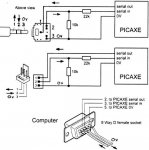
In all the minimum operating circuit diagrams, the 3 pin header is shown as the download cable connection with its pins numbered 1,2,3.
However on the USB and the Serial download circuit diagrams (pages 33 and 34 of manual ver 6.4b) where both the phono jack and socket, as well as the 3 pin header plug and socket circuits are shown, confusion may arise.
For the 3 pin header, both socket and plug are numbered 1,2,3.
For the phono plug and socket, only the plug is numbered 1,2,3 and these numbers do not correspond to the numbering for the 3 pin plug.
Recommend that;
a. the phono socket gets some numbers
b. that perhaps the phono plug and socket use a,b,c instead of 1,2,3 making it absolutely clear that these are different systems with different connection sequences.
Even better, for the phono plug diagram, the socket could be rotated anticlockwise 90 degrees and the plug placed to the left of it instead of below.
On checking through Manual 1, I feel there is a documentation issue which may contribute to the numerous problems new users have.
In all the minimum operating circuit diagrams, the 3 pin header is shown as the download cable connection with its pins numbered 1,2,3.
However on the USB and the Serial download circuit diagrams (pages 33 and 34 of manual ver 6.4b) where both the phono jack and socket, as well as the 3 pin header plug and socket circuits are shown, confusion may arise.
For the 3 pin header, both socket and plug are numbered 1,2,3.
For the phono plug and socket, only the plug is numbered 1,2,3 and these numbers do not correspond to the numbering for the 3 pin plug.
Recommend that;
a. the phono socket gets some numbers
b. that perhaps the phono plug and socket use a,b,c instead of 1,2,3 making it absolutely clear that these are different systems with different connection sequences.
Even better, for the phono plug diagram, the socket could be rotated anticlockwise 90 degrees and the plug placed to the left of it instead of below.
Last edited: