Download cable - Clarification

BCJKiwi

Senior Member
Having issues with download cable on a circuit which caused me to review the current information and re-check the cables in use.

On checking through Manual 1, I feel there is a documentation issue which may contribute to the numerous problems new users have.

In all the minimum operating circuit diagrams, the 3 pin header is shown as the download cable connection with its pins numbered 1,2,3.

However on the USB and the Serial download circuit diagrams (pages 33 and 34 of manual ver 6.4b) where both the phono jack and socket, as well as the 3 pin header plug and socket circuits are shown, confusion may arise.

For the 3 pin header, both socket and plug are numbered 1,2,3.
For the phono plug and socket, only the plug is numbered 1,2,3 and these numbers do not correspond to the numbering for the 3 pin plug.

Recommend that;
a. the phono socket gets some numbers
b. that perhaps the phono plug and socket use a,b,c instead of 1,2,3 making it absolutely clear that these are different systems with different connection sequences.

Even better, for the phono plug diagram, the socket could be rotated anticlockwise 90 degrees and the plug placed to the left of it instead of below.
 
Last edited:

BCJKiwi

Senior Member
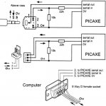
Here is what I believe the diagram in Manual 1 page 34 should look like.

If you print this off, the diagram should fit in the same space as the diagram in a printed page 34 from manual 1 (ver 6.4b).

Naturally the other diagrams scattered throughout the manual(s) should be updated to match.

The attached diagram is corrected so you can disregard Hippy's comment in post #5 below.

Replaced .pdf with improved graphic download4.jpg
 

Attachments

Last edited:

hippy

Technical Support
Staff member
I really do not understand where the confusion is coming from and I am not sure this is really helping anyone who is confused, especially as the information being given in this thread does not match with the Rev-Ed manual or the results of my testing.

The diagram in the manual is correct as best I can see and I checked against genuine Rev-Ed Molex and Jack download cables and socket on pre-built Rev-Ed boards. That matched with what the Rev-Ed manuals show ...

All PICAXE-side numbering is Molex equivalent. This does not necessarily match with whatever may be printed on the Jack Socket ... This is perhaps what is causing the confusion ?

Code:
[b]Official Rev-Ed Download 3-pin Molex[/b]

RX 9-way 2 <----Orange----- 1 Serial Out
TX 9-way 3 -----Red-------> 2 Serian In
0V 9-way 5 -----Brown------ 3 0V

[b]Official Rev-Ed Download 3.5mm Jack Plug[/b]

RX 9-way 2 <--------------- 1 Sleeve Serial Out
TX 9-way 3 ---------------> 2 Ring   Serial In
0V 9-way 5 ---------------- 3 Tip    0V

        .-----._____ ___ ___
        |     |_____|___|___>
        `-----'  1    2   3
                 |    |   |
RX 9-way 2 <-----'    |   |
TX 9-way 3 >----------'   |
0V 9-way 5 ---------------'


[b]Official Rev-Ed Download 3.5mm Jack Socket[/b]

Viewed from top, pins facing away

        .--------< 1 Serial Out
  .-----|-----.
 _|     |   o-|--> 2 Serial In
|_|     o     |   
  |         o-|--- 3 0V
  `-----------'
Nice. Very clear. I like the directional arrows.
Unfortunately they are not correct, nor is the Jack Socket to Molex numbering correct.
 
Last edited:

BCJKiwi

Senior Member
Corrected all the posts and diagrams to match the Official pinout.

Sorry Hippy but have never found anything in the manual that begins to resemble the diagram in your post #5 - just wish that had been in the manual - perhaps I have not looked in the right place(s)?

I still believe the manual should be updated with a much improved diagram. Despite your not understanding how others are confused, there are many who have trouble with this download cable so anything that can help will be of benefit.
 
Last edited:

womai

Senior Member
One question that I always have with connector pin assignments - is it a back view or a front view of the connector? That goes for the DB-9 connector of the download cable as well. I know DB-9 connectors often have the numbers embossed in their plastic parts, but white on white is easy to miss especially for a beginner who may not think of looking for them.

A true 3D picture of the connector + cable leading away (or a clear photo of the same) would clearly help in that case.

Wolfgang
 

BCJKiwi

Senior Member
@Womai
Page 34 manual1 and the download3.pdf file above is pretty clear on that - it seems about the clearest part of the diagram to me. With the added arrows in the download3.pdf diagram you really don't need to bother about the pin numbers.

The Phono socket states that it is a 'view from above'
 
Top