Diagram Needed
- Thread starter TAMeyer
- Start date
Not Work
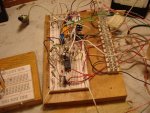
Help needed ASAP circuit does not work.Do not have schematic (all in my head) plz,,plz,, need to fix ASAP photo attached.
Help needed ASAP circuit does not work.Do not have schematic (all in my head) plz,,plz,, need to fix ASAP photo attached.
Attachments
-
 144.7 KB Views: 39
Bet a guinea somebody asks what these are.
As for me I'm kinda partial to leagues and furlongs and such.
What is a guinea?Bet a guinea somebody asks what these are.
A country in West Africa.What is a guinea?
Approx 90p +VATWhat is a guinea?
or 87.5p +VAT if you are reading this next year!
OK I'll go back to sleep again now.
Chavaquiah
Senior Member
Which one? Equatorial, Bissau, Conakri, Papua New Guinea or the old coin that can't be used with credit card readers?Bet a guinea
Twenty one Bob of course.What is a guinea?
I don't think my history mentions it. Perhaps you could refer me to that info. My copy of The Measure of All Things didn't mention it either IIRC. About all I'm aware of along those lines is the interesting association of the original Kilometer and the nautical mile.Miles is metric. Check your history.
Unfortunately I am not able to furnish any schematics of a metric mile but I did google it...
http://en.wikipedia.org/wiki/Metric_mile
A term of reference not an actual measurement.
Man we need an off topic section...........
http://en.wikipedia.org/wiki/Metric_mile
A term of reference not an actual measurement.
Man we need an off topic section...........
Are you trying to distract us?This IS the off topic section!
Tutorial: 1st Draft
All:
This is exactly what I had in mind when I promised a tutorial the other day.
That is to remove as much of the "time sink" aversion as possible that a new user would have when faced with creating a schematic.
The same aversion I had.
Until I spent days and days with Eagle did I begin to understand that my impetuous "just draw it, save it, get it done in 10 minutes.." would not work in this environment.
That is why the final drawing looks the way it does. A "compromise" of sorts.
But without a soliloquy, it is unclear if the tute's message is found by the reader.
So this question please:
.............does the direction taken in this document help the matter at hand?
All thoughts welcome.
Thanks
Terry
Attachments
-
371.6 KB Views: 36
Last edited:
hippy
Ex-Staff (retired)
I can see two problems; it's a rats nest of wiring which doesn't follow the traditional left-right flow of signal connections and readers have to guess what the connections are for components they aren't familiar with.
For example the 3093, which I'd guess was an op-amp without seeing a datasheet, but I have no idea of "rpe8". It's therefore hard to say if the connections to that are correct.
Added: Just saw the page after the circuit diagram which says what the 3093 and rpe8 are, but someone reading it would still have to open the datasheets and annotate which pin had what function.
It's definitely a step up from a photo of a breadboard, the first step people would have to make in determining the circuit, but whether it would suffice as a circuit diagram I am not sure.
Last edited:
A good first attempt Terry.
I must admit I thought it was going to be an article about drawing schematics from scratch rather than Breadboard conversion.
But, in fairness, you've put in a few good hours there.
Well done.
An extra page entitled "Straight lines make it easier to read" would be good.
And I can only speak for myself and say that a neater diagram gives me more confidence.
And avoiding lines sitting on text is essential.
Keep the IC symbol free of lines. Mark Pin 1.
I'm glad you've avoided colour. Whilst colour (a limited number) can make things clearer it is non-standard.
It's essential on a hairy breadboard though.
Also, the physical chip reference mark should be included.
You know, the dot or dimple they put on ICs to show which end is which.
Always ID the chip correctly. If needed call it IC1 or whatever and put a component list below.
But really depends on complexity of circuit.
Remember, one of the points of a schematic is to remove ambiguity.
And that includes words and phrases e.g. goober. I assume that means muck up?
Anyway, that was a good article.
Blimey, don't you know where "mile" comes from?
Though I ws joking about specifically being metric.
I knew that when I was about 14.
We have to thank the Romans.
PS.
The Forum Server seems to have been on the 'Go Slow' for a day or two.
Can someone put some more coal on please. A few shovels should do it.
Last edited:
fritz42_male
Senior Member
Bob's my uncle!Twenty one Bob of course.
fritz42_male
Senior Member
Must be Windoze based and due for a reboot!PS.
The Forum Server seems to have been on the 'Go Slow' for a day or two.
Can someone put some more coal on please. A few shovels should do it.
westaust55
Moderator
I have uploaded my latest DIPTRACE component library which now includes the latest PICAXE chips being:
see here: http://www.picaxeforum.co.uk/showthread.php?t=10576
- 18M2
- 20X2
- 28X2
- 40X2
see here: http://www.picaxeforum.co.uk/showthread.php?t=10576
...what might be interesting would be to add a load of standard components to that library (7805, battery, R, C, L, diode, relay etc - no patterns needed) so that very quick (beginner?) schematics could be done just from within that library.
A lot of the time (and complexity) taken to do real schematics in Diptrace is actually finding the right component in the right library with the right pattern for the PCB (and making them if they don't exist) - but for diagram schematics for forums the PCB patterns are of no interest at all.
Then we could have TAM's tutorial (I really like the style - I could never write like that, but it works) with a branch in the middle of it...if you only have MSPaint do this, if you have Diptrace and the PICAXE/general components library, do this...
Thoughts?
westaust55
Moderator
Without checking, I think that you may find that many if not all of the components are already in the library created by Mycroft in the same thread. Certainly 7805, R and diode are from memory....what might be interesting would be to add a load of standard components to that library (7805, battery, R, C, L, diode, relay etc - no patterns needed) so that very quick (beginner?) schematics could be done just from within that library.
Diptrace seems to have a following here, I've never used it but I have tried to use Eagle and gave up in frustration after 10 minutes, and I've been using these sorts of packages for years.
Is there an argument for nudging those on the forum that are new into electronics to using a simple package (maybe Diptrace but NOT Eagle, we'll never see them again) and if such a package can be agreed on have some tutes about it (or as mentioned a fork in Terry's tutes to a Diptrace section) and examples of common circuits, ie relay driving etc etc.
On the Arduino site they have a "playground" with all sorts of examples for common circuits (unfortunately in an annoying "photo realistic" format), a newbie will post saying something like "I'm using the XYZ playground example but the LED doesn't come on". Straight up everyone knows what circuit they are trying to build, and can suggest the usual culprits like "Is the LED the right way around".
I suppose the equivelant here is the manuals, but they are static.
As for imperial measurements, the product of a demented mind. Thank God we changed over in the 70s.
There are only two imperial measurements that I still find useful.
Smidgen = roughty 9/64ths of a poofteeth
Poofteeth = 2/5ths of 5/8ths of naf-all.
westaust55
Moderator
inglewoodpete
Senior Member
Eagle also has a following here, perhaps by a less vocal crowd he says clearing his throat while climbing on a soap box.Diptrace seems to have a following here, I've never used it but I have tried to use Eagle and gave up in frustration after 10 minutes, and I've been using these sorts of packages for years.
I have to say it was a difficult system to learn but it does everything I want. And since I've not had to design a board larger than what the free version does, I don't feel inclined to learn yet another package.
You still use Imperial every day.
What's the pin pitch on your PICAXE chips?
And what's the usual pitch on breadboards? (obviously horse and cart).
And sometimes when we mix units we end up with a very expensive SPLAT! on Mars.
I agree, metric is so much easier.
Whilst Pete gets off his disguised soapbox I'll add that I think it's a nice idea to have a single library with common components in a CAD package.
I've never used Diptrace and didn't like Eagle so I can't express an opinion.
But, to be honest, in the CAD that I use moving components into libraries takes about 10 seconds.
So, why can't some genius create a 'Commonly Used' library for BOTH CADs. Then we won't have the VHS/Betamax argument.
Is that Rocket Science?
The person who does it will have life-long fame on the Forum.
Where's Westy when you need him - he wants to be famous
And a marketing opportuinty for Rev-Ed; printed pencils, erasers and rulers.
Actually the rulers could have stencil hole/cutouts so people could do components too.
Why 2.54mm of course.What's the pin pitch on your PICAXE chips?
Found a New Tool
Gents:
I read every word of your replies and am appreciative for the feedback.
Frustrated with my results and how long it took, I went searching.
This method still requires "Paint", but the drawing process both easier and faster.
I don't have time this morning for a full rewrite, but the attached should be enough to allow comment.
http://www.qsl.net/wd9eyb/klunky/framed.html
Thanks
Terry
Attachments
-
 22.8 KB Views: 23
BeanieBots
Moderator
And what's the pitch of an Xbee module?What's the pin pitch on your PICAXE chips?
And what's the usual pitch on breadboards? .