Diagram Needed

TAMeyer

Member
The quote below...
Get out of bed and give us a drawing. Spend 10 minutes on a lovely sketch. Otherwise you'll get 50 replies (possibly based on ambiguous information) and you'll only read the last three.
http://www.picaxeforum.co.uk/showthread.php?t=16734

...prompts this idea.

My guess is that many of those who ask for help are new to the platform.

Posting files to a web site is a familiar practice for the technically minded. But in thinking through a tutorial for this problem I (believe so at least) found a key roadblock.

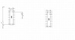
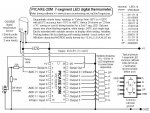
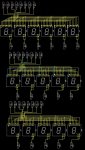
It is in first thinking of the best/fastest means to draw and capture the circuit that can bog you down.

Do you:
-Use "Paint"? Editing becomes cumbersome after a few lines.
-Surf for a quick drawing app? 10 mins of searching, still too long. "I could have drawn the circuit by now".
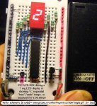
-Hand draw, and photograph. What if you don't have a card reader or the camera's transfer cable handy? Cellphone snaps...are often poor with detail.

If under deadline, I would have given up and just written.

Idea: Make it easy.

Reply to all circuit questions with:
Questions submitted with supporting diagrams receive priority attention.
Create your drawing "here". http://www.rev-ed.co.uk/picaxe/pebble/

How many people who hit this board cold, know this online tool exists?

Perhaps a special "fixed" breadboard version that can be automatically linked to a post? Or simply a drop down with steps including Alt-PrtScn for resized window capture, then dump to Paint.

In sales the mantra is "Make it easy for them to buy".

Perhaps this would help?


Terry
 

Dippy

Moderator
Nice idea and Westy has done a lot of work on that AND it has been suggested before.

BUT, most people here who are capable of detailed assistance and experienced with electronics use standard schematic diagrams for design.

I know of at least 10 people here who are experienced electronics designers, mostly hobby but a couple of Pros that are keen to help.
BUT would they so keen if they had to TRANSLATE pebble to a proper schematic?

I , for one, couldn't be arsed to translated a dirty great PEBBLE to a proper schematic. I could screw up in the translation.
If you want my help then people have to make it easy for ME.
Give me a schematic and give me links. Then give me a tenner.
Others are far more generous (and have plenty more spare time) than me as I am a grumpy git. :)

Novices will make more mistakes doing a breadboard.
And mistakes are far harder to spot on a breadboard diagram.
Then there may be mistakes when translating Breadboard to schematic.
It'll probably result in even more interrogation posts.

To my mind, if you are taking electronics seriously then you SHOULD have the tools to carry out your hobby or trade.
Whether this be a CAD package, or pen+ruler+scanner/camera.
And if you take electronics even semi-seriously then you SHOULD be learning standard schematic designs.

If I took up knitting then I'd buy some needles and learn to understand patterns.
If I take up Golf then I need shooting.

So, IMHO, no thanks. Though others will/may think differently.
 
Last edited:

MartinM57

Moderator
I'd rather not decode a PEBBLE to be honest - error prone at both ends and a very cryptic version of the standard electronic schematic layout everyone uses.

No excuse, if as D says you are serious, and your pen/paper/scanner fail, not go to www.diptrace.com and get the best (YMMV) freebie schematic program, spend 30 mins learning the basics and then cut'n'paste here...

I've just drawn a schematic for a display board with 16 various sized 7 segment LEDs and a 2x20 IDC stylee box header (so 200 pins) with a board size not much bigger than the displays themselves (displays on the front, header on the back between the pins of the displays) and its done a phenomenal autorouting job on a double sided board (14 thou tracks and gaps and about 100 19thou vias - so I'll not be making that myself) - in about an hour.

Diptrace - good for nothing, including 5 component schematics for posting here :D
 

hippy

Technical Support
Staff member
I personally prefer a circuit diagram than having to decode a built circuit photo or a breadboard layout. The more complicated the circuit the harder photos and layouts becomes to understand and time taken for everyone doing decoding adds up.

The quick solution is to hand draw and photograph or scan. A tip there is to use a thick felt-tip so things are still clear when viewed at reduced size.

A scrawled effort in Paint or something else is okay as long as it's understandable.

I like ASCII-art which is put between [code]...[/code] tags and cut and paste. Not everyone likes it so much and it does take practice to get things to look right but you don't need anything but a text editor.

Not all problems need a circuit diagram but some do and the more help given to help people understand what's being discussed the better. It's about making it easier for others to help yourself so a little effort can go a long way.
 

cdngunner

Senior Member
I know of at least 10 people here who are experienced electronics designers, mostly hobby but a couple of Pros that are keen to help.
BUT would they so keen if they had to TRANSLATE pebble to a proper schematic?

I , for one, couldn't be arsed to translated a dirty great PEBBLE to a proper schematic. I could screw up in the translation.
If you want my help then people have to make it easy for ME.
Give me a schematic and give me links. Then give me a tenner.
Others are far more generous (and have plenty more spare time) than me as I am a grumpy git
I think most people here are beginners or hobbyist. If us "dumb" people knew what the hell we were doing this site would be redundant and so would your input.

Just pointing out that some of us may not be able to give you (good?) schematics because of our limited electronics background. I'm still confused as to wether i sould be using electron flow or conventional flow.
 
Last edited:

Dippy

Moderator
I'm a little confused, CDNG.
You quoted hippy's post in full, and made a comment.
And you put "dumb" in quotes - I'm in the dark as to the point you make...?

I'm sure it's perfectly clear to others, but then again I'm the thickest person on the Forum.:(

Anyway, this will cause a digression and also we'll now probably launch into my Favorite CAD so I'll leave you to it. (Except to say: I know how BeanieBots feels about this too. I don't think you'll convince us Terry :) )
 

MartinM57

Moderator
we'll now probably launch into my Favorite CAD so I'll leave you to it
Have I mentioned Diptrace to the forum before....if not....:D

You ought to get a copy D - then we can all look at DippyTraces embedded in your off-the-cuff one page tutorials.....
 

Dippy

Moderator
I've never used Diptrace.

Some people here love it.
I can't get on with Eagle but many like it.
I use Seetrax Ranger but some aspects drive me up the wall.
Ditto EasyPC, but I reckon you get most bang for your buck with Easy PC.

Mind you, now that Farnell own Eagle I think you'll se some clever BOM tricks.
 

hippy

Technical Support
Staff member
Just pointing out that some of us may not be able to give you (good?) schematics because of our limited electronics background.
That does beg the question how people are building their circuits without having a circuit diagram as the template for doing that ?

I'll accept that simpler circuits can be thrown together without a diagram but as one gets more complicated that seems to become a basic necessity. If someone cannot describe what they have in terms of a circuit diagram then how do they know they've created what they need or want ?

Maybe I'm missing something or just have a different approach. One can build a circuit ( or other things ) without any plans or diagram but if something goes wrong there's nothing to compare it against to check its validity or where things went wrong. Perhaps it's the lack of circuit diagrams as the basis to start from which is the root of some problems ?

The members here are appreciative of varying skill levels ( including lack of them ) and will usually go the extra mile to help. Obviously a good circuit diagram is best, but something is usually better than nothing.
 

cdngunner

Senior Member
Someone does not neccessarily need to know how to schematically represent a relay to use one.

Much the same can be said for some of the electronic devices out today. I have used PLC's for quite some time, even programmed them. Still, I would be hard pressed to produce an electronic schematic of how they work even if my life depended on it.

Just saying........:)
 

KMoffett

Senior Member
Someone does not neccessarily need to know how to schematically represent a relay to use one.

Much the same can be said for some of the electronic devices out today. I have used PLC's for quite some time, even programmed them. Still, I would be hard pressed to produce an electronic schematic of how they work even if my life depended on it.

Just saying........:)
But, that's akin to not drawing all the internal components of an IC on a schematic.


A PLC is not a standalone device...it must be "attached" to power and input signals and output devices. If you were required to deliver information so an electrician or tech could wire up and debug even a minimal PLC system, they would expect an industrial wiring schematic.

Learning, using, and drawing schematics (even simple sketches) are part of learning electronics...beyond a switch, a battery, and a bulb. It's our universal (mostly ;) ) language of communications in electronics.

Ken
 

cdngunner

Senior Member
Learning, using, and drawing schematics (even simple sketches) are part of learning electronics...beyond a switch, a battery, and a bulb. It's our universal (mostly ;) ) language of communications in electronics.

Ken
Yes I fully agree, some of us are starting from scratch thought. Since I have been on this forum I have easily doubled my electronic knowledge, which ain't saying much.

One day I hope to be able to do a schematic which meets with Hippy's approval. :D
 

eclectic

Moderator
Just general comments.

Nothing can replace a high definition photograph/ scan.
There have been many instances,
where Forum experts have solved problems
due to wiring / resistors / polarity …......

Manual 3 has lots of mini-schematics.
Questioners may need to look at them, or be referred to them.
They may also learn a few symbols and conventions.
(Like I did) :)

And finally.
For the questioners that may need a starter.
How about providing a few simple drawings,
with dots that can be joined..
And that's not condescending
but facilitatory.
(If it's not a real word, then I've just made it up. :)

e
 

Attachments

BeanieBots

Moderator
I know how BeanieBots feels about this too. I don't think you'll convince us Terry :) )
My take is quite simple, I can't be bothered to help those who don't help themselves. The rest was put very politely by Dippy;)

I'd rather not decode a PEBBLE to be honest
Nor would I. In fact, I'd probably ignore such a post and also posts which simply give an artwork without a circuit. Quite frankly, anyone who has done an artwork without a schematic is plain dumb because what was the artwork designed to?

Someone does not neccessarily need to know how to schematically represent a relay to use one.
True, but if you want to discuss it with somebody else, you DO.

If you want to get by in a foreign country, you can do so without knowing the local language, but if you want to do more than gesticulate for food and drink without knowing what type will arrive, then learn the language. Otherwise you will become known as "the chicken" because that's the only food you can describe:eek:

I admire those who can knock up a diagram in seconds and/or do simple diagrams in ASCII art. I can't because I'm a spoilt old fart that has the luxury of having somebody else to do that for me. However, I still have to give them a drawing done in pencil on the back of a fag packet. These are legible enough to be scanned if required.

When doing diagrams, please follow the 'grammer' as well.
Just like english is made up from proper sentances, starting on the left and working its way across and then down the page. There are guidlines for schematics which make them easier to read.
Signals should flow from left to right. Power should flow from top to bottom.

Learn the language or get left out of the conversation.

PS.
I fully agree with what KMoffett says too.
 
Last edited:

techElder

Well-known member
If you don't have the ability to schematically represent an electronic circuit, then you are destined to be a 'mechanic' in electronics. You'll just be connecting components with screws to terminals with color-coded wires. You'll never know what's in those 'black boxes' or how they function.

Someone that ignores the need to learn how to draw a schematic just doesn't have the interest in electronics to go forward. IMHO.
 

Dippy

Moderator
The next time you want to get planning permission for a building take a picture of your plans made using Lego bricks.
Show it to your Architect and your local Planning Office.
Guess what they'll say...?
The sentence may end with the word "off". ;)

Oh no, Stan's going to tell us all about breadboards .;.

Mind you , what about Westy doing a version of PEBBLE with schematic graphics?
(Just promise me you won't call it an 'emulator') :)
 
Last edited:

manuka

Senior Member
Come on gents- this is 2010- it's hard to see what you're getting lathered about. Given the abundance of cheap digital cameras & nifty graphics editors,it's easy (ESPECIALLY for kids) to rustle up lucid insights to almost anything. Check the 20M/DS18B20 example below. Surely the issue with hazy Forum posts relates not to the tools so much as motivation to use them!

Dippy: I beg to differ about your "lego models",as building and engineering concepts still often are explored with simple but LUCID techniques and models. These may especially suit sweet talking the neighbours over the fence! Many decades ago (pre PC) I recall a cardboard & tape model of a nifty building extension I'd in mind successfully swung the rubber stamp my way at the bank. Stan.
 

Attachments

Last edited:

hippy

Technical Support
Staff member
One day I hope to be able to do a schematic which meets with Hippy's approval. :D
That shouldn't be hard as I quite likely have a higher tolerance than some members here. It is also more the content than the form which is important. Block diagrams can be just as useful as circuit diagrams as long as it conveys what needs to be conveyed.

My own circuit diagrams are usually like eclectic's 'join the dots' attachment, hand drawn on 1/4" graph paper.

I'm not adverse to cutting out photocopied IC pinouts, pasting onto A3/A4 and drawing the rest in. Enlarge IC's, paste onto A2 then reduce to A3 and you get a pretty good circuit diagram; good enough to have the resident CAD experts design a PCB from.

I suppose that's core to having circuit diagrams; you can pass what you want to someone who does it. It's also how you'll replicate or debug what you've created when you've forgotten what you've got on the board and how it's all meant to work.

An advantage for posted circuit diagrams not mentioned so far is that it's reasonably easy for someone else to scribble on and throw back quickly, show what needs to change rather than try and describe that, and it gives a solid reference when something is described.
 

Dippy

Moderator
Haha Stan, I knew you'd disagree... lovely. Reel him in :)

Building concepts are very frequently explored with models.
ABSOLUTELY. So are bridges, planes, cars, kettles and spectacles.
But they are scale models, built by craftsmen AFTER the (at least good preliminary) engineering drawings have been done. Not LEGO blocks. And not INSTEAD of technical/engineering drawings.
They may have done that in the time of Christopher Wren, but if you did that at my local Planning Office they'd hang you up by your putlugs.

And I honestly don't mean to sound like I'm having a go, because I use and appreciate breadboards for design and testing as much as anyone does. I love them. I want to have their babies.
But if someone posted your breadboard picture and said it doesn't work then I wouldn't bother.
A) I would have to translate it. I haven't got time.
B) I could make a boob.
c) Even worse with a real Breadboard is that little Johnny may have mucked up the connections and/or has duff components - leading to hours of fun with a dozen posts going back and forth with the usual Forum echo/repeats yawn.

Photos are, of course NSS, very handy. BUT we need to know that the circuit can work IN THEORY before diganosing a cockup. TWO different processes.
 
Last edited:

MartinM57

Moderator
Here you go - ~1hr work. It's not worth anything as there's a couple of problems, but imagine drawing that schematic (or launching straight into building a prototype without having it) ....
 

Attachments

Dippy

Moderator
"imagine drawing that schematic"
??
You just have - so I don't have to :)

But let's not get carried away (for a change).

Most people will be asking questions about a PICAXE a couple of transistors, an LED or two and a couple of relays. And, of course, the decoupling capacitor. And maybe a regulator without capacitors because they haven't read the data sheet.(kidding).
Components don't have to be bang-on world standard as long as they have an I/D. (and a link to a d/s where needed).

Pen, paper, ruler and scanner/camera 20 minutes.
If it's a blurred phonecamera then yuk, bye bye.

Martin, we appreciate your showing off, sorry, I mean showing us your skills.. ;)
 

TAMeyer

Member
Clarification

Pen, paper, ruler and scanner/camera 20 minutes.
My mistake in suggesting a breadboard tool...nice as Pebble is.

The idea is to encourage (strongly encourage) posters, especially new members, to include their circuit when asking a question.

When appropriate, I am suggesting that for those who do not include a schematic

...a boiler plate reply asking that an image be included with their post - and a link to a tutorial on 3-4 ways to create that image.

This is not meant to be rude or to suggest not answering questions without supporting documentation. It is to say "Please help us help you by providing us a layout of your circuit. If you are new to such a process, here are some ideas to make it easier."

If anyone sees value in such, I'll write a brief tutorial in the coming week.

Thanks

Terry
 

Dippy

Moderator
Yes, have a go Terry.

Just 2 things:-

1. "The idea is to encourage ...to include their circuit when asking a question."
- Good luck. We've been trying it for years :) (and praise to those that do actually go that extra mile to help us to help them!)


2. "a boiler plate reply..."
- if you include jargon in your tutorial please explain it.
I haven't got the slightest clue what this means and I can't stand Office/Corporate Speak, so I'm off for a bit of Blue Sky thinking, plant my flag in the sand and firm up later (ooer).
 

hippy

Technical Support
Staff member
It is to say "Please help us help you by providing us a layout of your circuit. If you are new to such a process, here are some ideas to make it easier."

If anyone sees value in such, I'll write a brief tutorial in the coming week.
Sounds like an absolutely excellent idea.
 

manuka

Senior Member
I've often requested a standard Forum header be issued for posters (especially new ones) to be prompted about the need for schematics & pictures etc. Hence how about the attached "alert" - ~1 minutes work.
 

Attachments

inglewoodpete

Senior Member
The next time you want to get planning permission for a building take a picture of your plans made using Lego bricks.
Show it to your Architect and your local Planning Office.
Guess what they'll say...?
The sentence may end with the word "off". ;)
When I was a teenager and my parents were planning their retirement home, I used Lego bricks to show the architect we they wanted for part of the house. The architect was able to draw what the folks wanted, and it was subsequently approved by the council's planning department. We'll never know if the architect use the "off" sentence after they left his office but he was polite in their presence (after all, they were paying for his new car/holiday/....).

So it can work. However, I wouldn't recommend taking the Lego model direct the the council ;)
 

westaust55

Moderator
Mind you , what about Westy doing a version of PEBBLE with schematic graphics?
(Just promise me you won't call it an 'emulator') :)
Sorry, but a bit busy at the moment with several large mining industry sized projects on the go.

However given time, it would be relatively easy using the same concepts as PEBBLE on a matrix basis. Would need to build up a library of component images. Would only need one "board"/sheet.

But I (like some others) use DIPTRACE for my schematics.
We already have two libraries with many PICAXE chips and related components here for the PICAXE community.

http://www.picaxeforum.co.uk/showthread.php?t=10576
 

westaust55

Moderator
I've often requested a standard Forum header be issued for posters (especially new ones) to be prompted about the need for schematics & pictures etc. Hence how about the attached "alert" - ~1 minutes work.
That example title is not a result of the Shaky Isles in action I trust :)
 

Attachments

MFB

Senior Member
Further to Dippy’s suggestion that simple schematics could be hand drawn for import via a digital camera. The result would be neater if graph paper was used to keep the size and spacing of the component symbols uniform. By careful choice of paper and pen colours it might even be possible to fade-out the background graph before posting. Many years ago I used green graph paper and a red pen to achieve similar results with a photocopier.
 

John West

Senior Member
I'm helping a 12 year-old boy learn electronics (build projects.) The first thing I taught him was that he had to draw a schematic. But the point being made at several places in this thread is that both youngsters and non-professionals in electronics are more "mechanistic" about their projects.

They haven't learned the methods or forms of schematic design yet - so requiring any ability with such design before we can help them with their physical electronics problem simply adds to their difficulties.

However - because we are working remotely here - such a drawing is extremely important to us if we are to help. It's a Catch 22.

I too have some degree of difficulty getting together such materials and presenting them in the forum - even though I well understand how to read and draw an effective schematic.

No camera - a questionable scanner - still learning how to best use the schematic design program I have - there are indeed lots of small impediments to presenting such info in a proper format to the forum.

Whatever we and the Rev. Ed. website staff can do to minimize the difficulty of creating and presenting such drawings would be most helpful.
---
Upon rereading this I think I've expressed my opinion but failed to offer anything of value to the conversation. Perhaps I should be on a government committee. :(
 
Last edited:

Dippy

Moderator
What!
In between multi-lingual Forum support, Westy has time for a job too?
His boss must be going up the wall. "Westy, have you done those triple integral diffusion equations for our new Interociter?"
"Non, pardon, sorry, no, I'm on the Forum." ;)


MFB: what's wrong with a pen/pencil and that strange device called a ruler? :)

Pete: There you go, you didn't use LEGO for the people that REALLY mattered.
QED. Tee hee.
But i'm more than happy to charge £100 per hour to translate breadboard to schematic. I doff my cap and tug my forlock in your general direction gentle sir if you pay up front!
 

MFB

Senior Member
Dippy, there is nothing fundamentally wrong with a pencil and ruler for drawing guidelines on a page but it’s probably more efficient to by ready made graph paper.
 

Dippy

Moderator
More efficient? Not if you have to drive 50 miles to get it :)
And it's more expensive pence/page than plain paper at my local shop 25 miles away.
 

manuka

Senior Member
More efficient? Not if you have to drive 50 miles to get it
And it's more expensive pence/page than plain paper at my local shop 25 miles away
Dippy: Is this the same "£100 an hour" consultant we all know (& tease)?? Things must be indeed grim in Blighty if such penny pinching is an issue -you should move to Australia (where the shops are only 20 miles away)!
 
Top