Designing and building PCBs

beb101

Senior Member
@SAborn

Your point is well taken. I guess the extra work satisfies the crafting instinct. I do however, find that solder mask makes soldering surface mount parts much easier and I also conserve on solder wick. There is some debate concerning tin whiskers on dense circuits, but I use it anyway (MG Chemicals Liquid Tin) because my circuits are not dense.

Baxter
 

SAborn

Senior Member

ZOR

Senior Member
Does anyone know of a PCB package that's very basic, i.e select an IC socket (no libraries), pads etc just basic component. Simple track goto there from here. Apologies for coming in on the professionals. Thanks
 

SAborn

Senior Member
ExpressPCB would be one of the simplest, and you can just use pads and join them with tracks manually rather than using the library foot prints.
The library foot prints are a bit crappy i think as they have large holes and small pads, not what you want for home use.

Just set the background grid to 2.45mm spacings and that will match any IC pins.

Its still my prefered package because it do what i tell it to, not what it thinks i want it to do.

And its FREE.

Simple schematic drawing package included...... bonus.
 

bluejets

Senior Member
Think I may have mentioned it before but anyhow, for those doing toner transfer be aware that some laser printers have toner that is NOT refusable.
Brother printers are in that catagory.

I had an old HP that worked fine until it died. Bought a Brother HL-2140 thinking all laser printers are the same and then had more strife than Flash Gordon.

Read about the problem somewhere and changed to a HP (P1102W) once again and all good now. I think the same would apply if you did not use original refills.

Use the blue toner transfer from Press N' Peel.
 

mrburnette

Senior Member
From my days at EPSON R&D - there are features in some SCANNERS and COPIERS to prevent counterfeiting.
There are none that I know of in the printers.
This may explain some of the color printer aspects: http://en.wikipedia.org/wiki/Printer_steganography

I have heard rumors for years about some "public" copiers such as are in libraries and post offices embedding 'errors' into the printouts such as device serial numbers. I cannot attest the truth of this, but my information came from manufacturer representatives while I was working as an IT architect in a Fortune 100 company.

The rumor about differential reproduction size is something I remember from way-back, perhaps the late 80's. It has been so long that I have no idea of whether the issue was with mis-aligned or designed-that-way optics in photocopiers. I cannot remember ever hearing the size issue described in reference to laser printers, however.

Such rumors are difficult to verify, excepting the Wikipedia link above in regard to color printers. Honestly, in today's tech, almost anything could be done and with proprietary printer drivers, no company would be required to make that information public, IMO.

- Ray
 

mrburnette

Senior Member
I just looked up the MG Chemicals Liquid Tin and see its available locally through Mektronics, i might get some for a go, currently i use a solder paste and paint the board with it, then heat with a hot air heat gun to flow the solder paste over the copper, then wash the excess off in water.

MG Chemicals Liquid Tin looks easier;)

http://www.mektronics.com.au/index.php?page=shop.product_details&flypage=flypage.tpl&product_id=2167&category_id=204&option=com_virtuemart&Itemid=57
A less expensive product is "Tinnit" when you can find it....
http://www.minute-man.com
One pint, about $8 U.S.

Tinnit.jpg
 

bfgstew

Senior Member
Well I have made my first PCB last night, well, when I say made I meant etched. Layout designed using DesignSpark, all chemicals bought from http://www.megauk.com/pcb_chemicals.php and equipment all homemade. Just need to drill and build it (this Saturday). Will get some pics so you can see how well it came out.
Am going to have a bash at the silkscreen method mentioned earlier in this thread using the backing paper off a label.
 

Goeytex

Senior Member
The rumor about differential reproduction size is something I remember from way-back, perhaps the late 80's. It has been so long that I have no idea of whether the issue was with mis-aligned or designed-that-way optics in photocopiers. I cannot remember ever hearing the size issue described in reference to laser printers, however.
Imagine the nightmare this would be for Engineering / Design companies that rely upon an accurate reproduction. I highly doubt that it is true.
 

Jakob2803

Senior Member
If anyone is interested, I did not use ferric chloride but mixed my own batch of acid. It's a recipe off of Instructables. 2 parts hydrogen peroxide 3-10% and 1 part hydrogen chloride 30%. Works well. :eek:
 

bfgstew

Senior Member
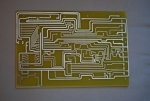
Here is my first attempt at making a PCB, this is the lower board, I have another to make which fits on top of this one, along with a OLED screen and keypad matrix.

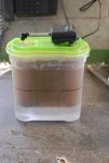
3 minute exposure time and 45 minutes in etching tank (only reason for that is the solution was everso slightly over diluted)
Tracks are spot on, nice and crisp and defined. Finished off with 15 minutes in a tinning bath.

pcb.jpg
 

bluejets

Senior Member
I'd like to hear a bit more about how you did that. Looks a lot better than my first attempt, actually looks a lot better than the last one i did too.
Very good work.
 

bfgstew

Senior Member
Am doing second board on Saturday, so will take some pics of set up and kit I have made, so you can see how I do it.

Probably just beginners luck........................:p
 

bfgstew

Senior Member
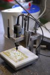
All knocked up from surplus kit, parts etc, so cost was minimal to say the least.

pcb-drill.jpg
 
Last edited:

John West

Senior Member
When using Jeremy's technique, be sure not to put printed paper beneath the PCB. I did that and wound up with newsprint "transferred" onto the bottom of my PCB, which I then had to remove with a Scotch-brite in order to iron-on the correct image.

-

bfgstew, I like your drill-press. I purchased a genuine Dremel drill-press after using a cheapie knock-off that jumped around as I was applying pressure, tending to break tiny bits. The Dremel brand press jumped around, too. Your home-brew press looks like something that might actually drill straight.
 

bfgstew

Senior Member
It drills fine, even with HSS drills down to 0.3mm, the only trouble is the Dremel is rather noisy and does vibrate a bit, put this down to it being built on the cheaper end of the market - bearings are not high spec and by the sounds (and feel of it) the rotor is not fully balanced, still it does the job, so not going to complain (much)!
 

Dippy

Moderator
Home drilling reliably with 0.3mm is impressive.
Shanked or 'jobber'?
The Dremels I used at my old workplace were pretty unimpressive.
Maybe knackered or abused I don't know but they were poor. Shakey and wobberly.

At home I use a Proxxon micromot.
They are offered with collet or 3-jaw chuck.
Collet style is better for precision.
The drill bearings are quite impressive for a relatively inexpensive drill. Made in Eu.
Not as good as a Westwind Air Bearings spindle but a little cheaper :)
 

bfgstew

Senior Member
These are jobbers and my Dremel has a brass 3 jaw collet fitted which helps a bit, still not the best in the world.
 

dbarry722

Member
Jeepers!!

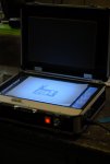
Was always wondering what way I could build a double sided exposure unit and there it is staring me right in the face..

An aluminium flight case :p

Cheers

Declan
 

bfgstew

Senior Member
Just make sure that the distance between the U/V lights and the glass are equal otherwise it will cause exposure problems.
 

dbarry722

Member
Just make sure that the distance between the U/V lights and the glass are equal otherwise it will cause exposure problems.
Cheers.. Will do. Mind you, that's a long term project. What i'm looking at the moment is seeing if it works out cheaper at moment to outsource my pcb's. The problem is, here in the uk its expensive from what I can see. It actually works out cheaper to get them done in Austrialia than the uk and that is with shipping included. I'm looking to see if something similar is available in Europe that might work out cheaper.

Declan
 

Dippy

Moderator
It might just be my shaky hands, but I can't recommend <0.8mm tungsten carbide bits for rough hand drilling. Ting! Ouch!
 

Pongo

Senior Member
It might just be my shaky hands, but I can't recommend <0.8mm tungsten carbide bits for rough hand drilling. Ting! Ouch!
Hand held drill? If so I would have to agree, but I don't have any problem with using them in my drill press (regular 0.5" one, not a mini).
 

bfgstew

Senior Member
To combat poor eye sight and a shaky drill, when I do PCB's I make the pads slightly larger and the hole slightly smaller, this gives the drill something to 'centre' on, seems to work for me as not had a seriously out of line hole, yet!
 

marzan

Senior Member
I had an idea. While collecting parts for a Dlp projector to 3D printer conversion I wondered weather anyone has used a projector to expose light sensitive pcbs? Then had another thought. Could do the same for the solder mask? Dlp projectors are capable of curing uv sensitive polymer so should be possible.
 

marzan

Senior Member
Texasclodhopper:279379 said:
I'm wondering if you could hold the image steady enough for a long exposure time?
If you look up 3d Dlp printers, they have better resolution than filament printers. The only issue that needs to be sorted is getting the projector image small enough to get more intense light. Im thinking of a dual purpose machine. Mirror to flip image up to use the 3d printer and down to expose pcbs / solder mask
 

marzan

Senior Member
Just found a site for a program called FLATCAM. Pos processor for Gerber files so would work with most pcb design programs. Has some nice features like cutout tabs, but possibly could be the best one is mirroring using locating pins. Well worth a look.
 

beb101

Senior Member
I have been wanting to try this,
http://research.microsoft.com/en-us/projects/papercutterpcbs/
His short youtube video is an impressive proof-of-concept for both milling and drilling.
However, I would use the cheaper Silhouette Portrait ($139). The only difference
between this model and the Cameo is banner cutting.

This is a very versatile machine. It can also cut solder stencils,
http://www.idleloop.com/robotics/cutter/index.php#stencil
http://dangerousprototypes.com/forum/viewtopic.php?f=68&t=5341&start=15

It should also be fairly easy to do UV exposure with a high power UV LED, some optics,
and the Silhouette pen accessory.
 

marzan

Senior Member
Have been using flatcam now for a couple of weeks. Has some nice features. You can use location dowels to flip your board for 2 sided PCB`s. as you can see in the photos the lineup is pretty good. the board was drilled from the other side. depth wasn`t set quite right, hence the not quite through holes you can see. another nice feature is the tabbing when cutting out the board.board1.jpgboard2.jpg
 
Top