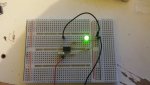
Step 1
Point A shorted - LED OFF
Point A floating - LED ON
That's a pass, good so far.
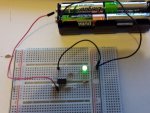
Step 2
Point B shorted - LED OFF
Point B floating - LED ON
That's a pass, so still good.
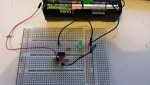
If I then do step 3 with the regulator and power pack, I get these results
Point B shorted - LED ON (the LED seems to blink a little)
Point B floating - LED ON
That is a fail and we are now identifying what the problem may be.
The power supply or circuitry appears to bring some sort of issue which causes the PICAXE on-chip comparator to activate when it should not. This is why we are doing it a step at a time to see where things stop behaving as expected.
The question now is; why is the power supply causing problems ?
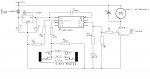
Rossko77 is correct that the circuit should have a 100nF (0.1uF) cap across the PICAXE supply and there may be other capacitors required around the regulator.
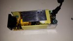
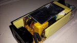
It is probably time to detail all the parts of your power supply, all components including the wallwart / plug-in module; what is that rated at, voltage, current, AC or DC ?
NOTE: If I change the 100k resistor to a 22k resistor then I get these results
Point B shorted - LED OFF
Point B floating - LED ON
There are three possibilities as I see it; noise or ripple being introduced at Pin 4 which is taking the on-chip comparator above its activation point, or noise and ripple being introduced on +V or inside the PICAXE which is causing the on-chip comparator to activate, or a combination of both.
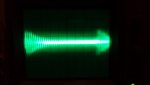
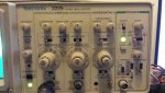
I would at this point normally recommend using a scope to see exactly what the signals are doing; on PICAXE +V, at the 100K to 47K junction, and at pin 4 of the PICAXE.
I am betting you don't however have a scope, so, before simply throwing capacitors at the problem, tweaking resistors, or making guesses as to how we can best fix things we need that full circuit diagram of the power supply.
While reducing the 100K seems to solve the problem that feels to me to be simply masking whatever fundamental issue there is. My test setup works as expected with a 470K pull down so it is intriguing why your setup does not work with 100K. While we can probably bash it into shape and make it work it would, to me, make sense to understand why it does not work.
With 100K plus 47K I can activate the LED by touching the sheaved wire between the 47K and pin 4 or the join between the 47K and 100K so perhaps the resistors are simply too high value, that they are prone to induced pick-up and it is simply that I don't have such induced pick-up.
A 100nF capacitor across pin 4 and 0V seems to overcome activation when the sheaved wire from 47K to Pin 4 is touched ( though not when the bare 47K/100K join is touched ) so perhaps that is a fix worth trying.

") I think the initial issue was down to a sensitivity problem. I tried the circuit on a different part of my desk (sound stupid I know). When I plugs the power pack it, it works, the LED didnt come on. But as soon as I put my hand close to the circuit it came on. I could literally turn the LED on and off by moving my hand towards and away from the circuit.
I think the initial issue was down to a sensitivity problem. I tried the circuit on a different part of my desk (sound stupid I know). When I plugs the power pack it, it works, the LED didnt come on. But as soon as I put my hand close to the circuit it came on. I could literally turn the LED on and off by moving my hand towards and away from the circuit.