Audio Signal as Switch
- Thread starter RustyH
- Start date
hippy
Ex-Staff (retired)
What is the source of the audio, its signal voltage, and how quiet / inactive is it normally ?
You can use digital inputs or on-chip comparators to detect when a signal is present if the voltages and nature of the signal allows it. The following worked for detecting composite video and may also work for audio ...
http://www.picaxeforum.co.uk/showthread.php?19289-Composite-video-signal-detector
I don't know if they are available in the UK, but FutureKit make such a kit. Look for the FK408, sound-operated relay with 240V in and out, adjustable sensitivity.
I use it for my anchor alarm, (see Anchor Alarm II thread), with a Picaxe in between the detection and the relay. Still having problems with ambient noise, more work to be done.
I use it for my anchor alarm, (see Anchor Alarm II thread), with a Picaxe in between the detection and the relay. Still having problems with ambient noise, more work to be done.
Are those device's not microphone activated, so if I have a conversation in the room its going to pick up a sound and turn the amp on. I actually want it to detect the sound signals from the 3.5mm jack when music is playing.
Or would I simply replace the mic in them schematics with a 3.5mm socket
Or would I simply replace the mic in them schematics with a 3.5mm socket
hippy
Ex-Staff (retired)
The audio signal should likely be around 250mV, maybe up to 1V peak-to-peak if 'line level'. I would expect the suggestion in post #3 should work.The source actually from HDMI to Audio Converter, on a 3.5mm stereo jack.
hippy
Ex-Staff (retired)
Audio signals are usually AC so a meter will generally average them out towards 0V on a DC setting, and will unlikely register on a 230VAC setting.My multimeter must be playing up then, cause I cant seem to read anything over 0.2mV!!
Audio signals usually have a high peak-to-peak amplitude so any electrical noise and ripple about 0V gets buried. Microphones and record deck pick-ups do have lower signals.
noelnelson
New Member
If the signal is clean (no noise) and stable frequency, use an amplifier or comparator to square it off to a 5V squarewave, feed it into any input pin, then use the COUNT command.
e.g. COUNT a 1kHz signal for a 1 sec period, which will save it to a wordvariable. Then test the wordvariable with if statements for greater than 990 and less than 1010, you can then turn on or off whatever with the IF directive. If the frequency is less stable, widen the IF parameters
e.g. COUNT a 1kHz signal for a 1 sec period, which will save it to a wordvariable. Then test the wordvariable with if statements for greater than 990 and less than 1010, you can then turn on or off whatever with the IF directive. If the frequency is less stable, widen the IF parameters
hippy
Ex-Staff (retired)
That's good to hear. I've always been a fan of 'zero component' solutions. Or at least no more than PICAXE, resistors, diodes, capacitors and LED's.Just got to say, the circuit and code you told me to give a go, works an absolute treat, thank you")
Probably easier to come from the other direction; USB provides 5V at up to 100mA ( and maybe more ). Really depends on what is supplying that USB power. The PICAXE will probably draw less than 20mA so the relay can draw up to whatever is left.How much power draw would the switch side of a relay use? Im wondering if I could power this the whole circuit from a USB port
hippy
Ex-Staff (retired)
Which model ? You should be okay for 100mA but earlier boards may need modding to bypass the USB polyfuses and I recall there may be ongoing issues with hot-swapping and in-rush currents resetting the entire PI and you might have to work round that.I would use the USB port of a Raspberry Pi
Might be easier to take power from the GPIO connector or the other 5V test points. You can run that power to a separate cable and USB socket and keep the two data USB ports on the Pi free for other use.
I'd probably add a diode inline and include a large reservoir cap on the PICAXE / relay side. Go for the highest relay coil resistance you can find to minimise current draw.
Take care if switching mains!
hippy
Ex-Staff (retired)
I think you need to check with the Pi manufacturer for a definitive answer.I think Ive found a relay with a lower current on coil. At between 72 - 80mA, so that should work on the GPIO pins
As I understand it the Pi is power limited. All power goes through a 750mA fuse ( schematic incorrectly shows 1.1A ) and the CPU can draw up to 500mA, leaving 250mA to be shared by GPIO power, USB ports and camera module if fitted. Nominally that's 100mA per USB port with 50mA spare for GPIO power.
You should be okay but it depends on what USB devices you are using. The more you draw through GPIO the less you have for USB, get close to the 750mA max and the PSU may start to sag affecting operation. The best solution may be a separate power supply for the PICAXE and relay.
hippy
Ex-Staff (retired)
Activating the relay might have the same effect on the supply as hot-swapping a USB device with its initial in-rush current which could cause a Pi reset so you probably will have to experiment. The Pi forums may indicate what levels of in-rush current are acceptable.Do I still need to be careful of current overload if its only on for a few milliseconds, or is there more room for maneuver??
Right, to save the hassle of pushing the RPi to its current limit, Im going to power the Picaxe circuit separately.
I plan to do this by using a 1.5A 5V USB Power supply, one of the ones with the female USB connector on the power plug. I will then use a Micro USB Y cable to power the RPi and also the Picaxe Circuit. Hopefully thats the neatest and easist way of doing it.
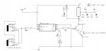
So based on that, I have done the below circuit. Ive included an LED off pin 5 to tell me when the Relay is on (wasn't such if I could do this off pin 6 as well??).
One question I do have, in the video circuit you posted Hippy, there is a 100k resistor between the video signal lines, would included that?
Any other issues you can see with my circuit as it?
Thanks
I plan to do this by using a 1.5A 5V USB Power supply, one of the ones with the female USB connector on the power plug. I will then use a Micro USB Y cable to power the RPi and also the Picaxe Circuit. Hopefully thats the neatest and easist way of doing it.
So based on that, I have done the below circuit. Ive included an LED off pin 5 to tell me when the Relay is on (wasn't such if I could do this off pin 6 as well??).
One question I do have, in the video circuit you posted Hippy, there is a 100k resistor between the video signal lines, would included that?
Any other issues you can see with my circuit as it?
Thanks
hippy
Ex-Staff (retired)
The 100K to ground was to stop the detector activating if the cable is unplugged. Probably best to fit it.
You should be able to connect the LED+R to pin C.1 so it activates when the relay does.
Also add a decoupling capacitor and a reservoir cap across the power supply.
You should be able to connect the LED+R to pin C.1 so it activates when the relay does.
Also add a decoupling capacitor and a reservoir cap across the power supply.
Hippy,
Having some real issues on the circuit, I had it working the other day, but now I can seem to repeat the success. For some reason it just turns X1 on straight away, even when nothing at all is connected to x4
Any ideas?
EDIT: Ive actually just discovered that if I plug the audio output (which I tested it first) from my PC monitor to the circuit, it works fine. But when I plug my ipod to the circuit, it doesnt work. What could be causing that?
Last edited:
noelnelson
New Member
Beware of connecting to other devices that are powered from an AC plug-pack. Many switchmode types have a floating DC output, i.e. floating voltage relative to the ac input and ground connection. My laptop floats at approx 90V above ground. If I connect the Picaxe USB serial cable to a picaxe device, while the power pack is on, it causes the picaxe to re-boot. Simiarly, I have a TV masthead amp that floats mid AC approx 115V. Connecting it to the antenna port on the wall when the plugpack is on causes quite a shock. Transformer type plug-packs dont have this issue. They are identifiable by being heavier.
So you need to check your ipod charger terminal voltages relative to your audio device, while they are powered but not connected together.
The simple fix is to connect the common lines (0V and ground) first, with a wire jumper, while joining the whole plug/socket together. this will drag the floating DC voltage of the plug-pack back down to the same reference level as the audio device.
hippy
Ex-Staff (retired)
I think it is best to stop and step back, explain how you mean and what you are now doing, before something seriously untoward occurs.I see what I have done wrong now, I was usingthe Ipod from battery source, but it seems you need to be connected to a common ground (mains neutral) for the circuit to work
I am not sure what the situation is since the earlier post where the circuit was behaving oddly, activating when there was no signal connected. If there is faulty operation it would be best to resolve that before proceeding.
Hi Hippy,
Ok
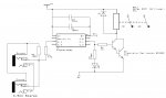
Firstly, I have decided to switch the 16v side of the power pack rather than the 240v side. So the voltage are a little less dangerous.
What I have found is that the circuit works fine when the audio jack is connected to something like my monitor or the RPi. However, the audio lead is disconnect, the circuit just latches on. Also, if I plug it in to an ipod instead, again it latches on.
But, if I then connect back to something like the monitor / Rpi, it works again
Ok
Firstly, I have decided to switch the 16v side of the power pack rather than the 240v side. So the voltage are a little less dangerous.
What I have found is that the circuit works fine when the audio jack is connected to something like my monitor or the RPi. However, the audio lead is disconnect, the circuit just latches on. Also, if I plug it in to an ipod instead, again it latches on.
But, if I then connect back to something like the monitor / Rpi, it works again
hippy
Ex-Staff (retired)
The design is using the on-chip comparator to detect small voltages on input pin 4. With no input connected pin 4 should be tied to 0V, albeit through a large resistance. Perhaps the resistance has become too high or something is introducing noise on pin 4 or within the chip which causes the comparator to activate. It could be that the amp is back-feeding voltage which is activating the comparator. Does disconnecting the cable to the amp make it work ?However, the audio lead is disconnect, the circuit just latches on.
You can monitor the raw output of the comparator on pin 2 with a LED+R or add SERTXD to show the state of the comparator COUT bit.
Perhaps post your current circuit to see what you have now. Are you still switching an active only when powered relay or using a latching relay ? The circuit may have become incompatible with the software or vice versa. Does the circuit behave correctly when battery powered ?
Hi Hippy,
If I removed the amp out of the equation (so just using an LED connected to out pin 1), then it still does the same
Input Audio connected to RPi = Circuit Works (LED on when music plays, Off when no music plays)
Input Audio connected to Monitor = Circuit Works (LED on when music plays, Off when no music plays)
Input Audio connected to Ipod = LED Latched On (LED on when music is off or on)
Input Audio disconnected = LED Latched On (LED on when music is off or on)
I also tried to connect the LED to pin 2, and the same as above occured
I then also tried to lower the pull down resistor right down to 22k, and it still produced the above results
Are you sure the resistor is both earthed and connected to the input line when the socket is empty? The pins of switch-type sockets can be confusing.I then also tried to lower the pull down resistor right down to 22k
(edited cos looking at wrong schematic)
Hi, If you look at Hippy's circuits form post #3, there is a pull down resistor between his Video in and Ground. So I have included this on my project board between the left channel (that Im sensing off) and ground. Originally this is called for as 100k, but Ive tried 47k and 22k with no effect
hippy
Ex-Staff (retired)
That's the only case you have to worry about for now.Input Audio disconnected = LED Latched On
That seems to suggest the comparator is seeing some voltage on pin 4 rather than 0V. What if you connect a wire from pin 4 direct to 0V ?I also tried to connect the LED to pin 2, and the same as above occured
I tested the original code here and it all works as expected. Have you edited the code in any way ?
My gut feeling is a resistor has come lose, there's a dry joint or it's a miswiring which wasn't noticed earlier because it was tested with a signal connected and that works, masking the underlying problem.
The odd thing is that my setup on an AXE090 board doesn't keep output pin 1 nor 2 high if I leave it floating, even with a wire attached and using myself as an aerial.
Could the 08M2 have been damaged while experimenting ? Do you have another to try ?
Hi Hippy,
Ive re-assembled the circuit on the project board, checked over it and fitted as new 08M2. However I still get the same situation as above. I noticed the when connected to the Ipod, its quite sporadic (sometimes on, sometimes off) and Im wondering if the metal back of the ipod causes some interference. Likewise, when the audio cable is disconnected maybe there is interference getting to it.
On the plus side, I dont think Im going to use it with an Ipod now, nor will it ever be disconnected. So I think the current solution will work for what I need it for