(Apparent) differences in DSM between 14M2 and 08M2

PhilHornby

Senior Member
I've been experimenting with the code in this thread to modulate a (PWM-derived) 125KHz carrier using the Data Signal Modulator. I've chosen to use the 'MDMin' pin to modulate the data - and this behaves differently on the 14M2 and the 08M2 (aka PIC16(L)F1825 and PIC12(L)F1840) - despite the datasheets being identical.

In a nutshell, the MDMin pin (C.0 on 14M2 and C.1 on 08M2) is the subject of 'output' commands such as HIGH and PULSOUT, but the DSM sees the signal as though it is an input.

All was fine, until I tried to take this signal to an external circuit, in order to generate 10µS pulse to fire a Triac. It seems that C.0 pin on the 14M2 pin is in full 'output' mode, whereas C.1 on the 08M2 behaves much more like an 'input' with the pullup activated. I want to generate the pulse on the falling edge of the signal and on the 08M2 there isn't a falling edge, unless I add a resistor to GND!

Is this expected? Is there something I can configure to change it to a 'proper' output? (I believe I've tried every thing specifically related to the DSM that might apply).

I can always add a some more hardware - but it would be nice if I didn't need to.

This is my code for initialising the DSM. Aside from the comments, it is identical on the two PIC(axe)s.

Rich (BB code):
symbol MDCON   = %11111100          ;Control
Symbol MDSRC   = %11111101          ;DSM Source select
symbol MDCARL  = %11111110          ;DSM CarrierLo signal select
symbol MDCARH  = %11111111          ;DSM CarrierHI signal select

;Data Signal Modulator
;Register 23-1 MDCON: Modulation Control Register

symbol MDEN=bit7  ;  1-------       ;Modulator module is enabled and mixing input signals
;MDOE             =  -1------       ;Modulator Pin output enabled (C.0 aka Serout on 08M2)
;MDSLR            =  --0-----       ;MDOUT pin slew rate limiting disabled
;MDOPOL           =  ---0----       ;Modulator output signal NOT inverted
;MDOUT            =  ----R---       ;Current value (readonly)
;unimplemented    =  -----XX-       ;Unimplemented
;MDBIT            =  -------0       ;Select LOW Carrier source (only when MDBIT selected in MDSRC)
symbol valMDCON   = %11000000       ;composite of above

;Data Signal Modulator
;Register 23-2 MDSRC: Modulation Source Control Register

;MDMSODIS         =  0-------       ;Output signal driving peripheral selected by MDMS<3:0> is enabled
;unimplemented    =  -XXX----       ;Reads as 0
;MDMS             =  ----0001       ;0001 = MDMIN port Pin (C.1 on 08M2)
symbol valMDSRC   = %0000001        ;composite of above

;Data Signal Modulator
;Register 23-3 MDCARH: Modulation High Carrier Control Register

;MDCHODIS         =  0-------       ;Output signal driving the peripheral o/p pin is enabled
;MDCHPOL          =  -0------       ;Selected High Carrier Signal is NOT inverted
;MDCHSYNC         =  --0-----       ;Modulator o/p is NOT synchronised to the high time carrier
;Unimplemented    =  ---X----       ;Unimplemented
;MDCH             =  ----0100       ;0100 = CCP1 output (PWM mode only). (Normally C.2 on 08M2)
symbol valMDCARH  = %00000100

;Data Signal Modulator
;Register 23-4 MDCARL: Modulation Low Carrier Control Register

;MDCLODIS         =  0-------       ;Output signal driving the peripheral o/p pin is ENABLED
;MDCLPOL          =  -0------       ;Selected Low carrier signal is NOT inverted
;MDCLSYNC         =  --0-----       ;Modulator o/p is NOT synchronised to the low time carrier
;unimplemented    =  ---X----       ;Unimplemented
;MDCL             =  ----0000       ;VSS
symbol valMDCARL  = %00000000       ;composite of above

      PokeSfr MDSRC,valMDSRC                    ;set Modulation Source Control Register
      PokeSfr MDCARL,valMDCARL                  ;set Modulation Low Carrier Control Register
      PokeSfr MDCARH,valMDCARH                  ;set Modulation High Carrier Control Register
      PokeSfr MDCON,valMDCON                    ;set Modulation Control Register
14M2 Base PIC datasheet
08M2 Base PIC datasheet
 

hippy

Ex-Staff (retired)
This is my code for initialising the DSM. Aside from the comments, it is identical on the two PIC(axe)s.
For the 08M2 it seems your configuration is correct, matches my calculations -

C.1 MDMIN = 0 -> C.0 Output Low
C.1 MDMIN = 1 -> C.0 Output matches C.2 PWMOUT

The same settings when used on a 14M2 should mean -

C.0 MDMIN = 0 -> C.1 Output Low
C.0 MDMIN = 1 -> C.1 Output matches C.2 PWMOUT

Which is the same, except C.0 and C.1 usage is reversed.

All was fine, until I tried to take this signal to an external circuit, in order to generate 10µS pulse to fire a Triac. It seems that C.0 pin on the 14M2 pin is in full 'output' mode, whereas C.1 on the 08M2 behaves much more like an 'input' with the pullup activated. I want to generate the pulse on the falling edge of the signal and on the 08M2 there isn't a falling edge, unless I add a resistor to GND!
I don't really understand what you are describing there.

Firstly in how you are using what you have to generate a 10us pulse on a falling edge. The DSM is a 2-input-to-1-output selector rather than a monostable.

Secondly what you mean by C.0 on the 14M2 seeming to be in output mode. How have you determined that ?

In a nutshell, the MDMin pin (C.0 on 14M2 and C.1 on 08M2) is the subject of 'output' commands such as HIGH and PULSOUT, but the DSM sees the signal as though it is an input.
Are you trying to control the MDMIN pin which sets the DSM by outputting to the MDMIN pin ?
 

PhilHornby

Senior Member
A bit more background: The circuit feeds OOK modulated 125KHz to a series L-C tank circuit. What I found, is that there is a tendency for the oscillations to continue after the signal is removed. I need to briefly fire a Triac to damp these down. (This concept is from a Microchip Application Note).
Are you trying to control the MDMIN pin which sets the DSM by outputting to the MDMIN pin ?
Yes. (As per example in the referenced thread). It works - at least as far modulating the carrier is concerned. What is different between the 08M2 and 14M2, is what happens when you try to use that low frequency modulating signal to drive additional circuitry. I need the low-going trailing-edge to trigger a 10µS monostable (of some description) which then gates a Triac.
Firstly in how you are using what you have to generate a 10us pulse on a falling edge. The DSM is a 2-input-to-1-output selector rather than a monostable.

Secondly what you mean by C.0 on the 14M2 seeming to be in output mode. How have you determined that ?
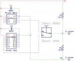
The approach shown here works with the 14M2, but not with the 08M2. C.0 on the 14M2 gives a nice square-edge signal, alternating between 0V and +5V. With the 08M2, C.1 appears to 'float' rather than being taken to GND - hence the addition of R5 (470R). Higher values of R5 work, but the higher it gets, the more round-edged the low-going signal becomes. In the case of the 08M2, there seems to be insufficient current flowing to reliably trigger the Triac. I originally used an NE555 monostable to generate the pulse - but it still needed the C3/R3/D4 arrangement - because the trigger lasts longer than the output pulse. Suggestions for alternative means of generating the pulse welcome!

25838
 
Last edited:

hippy

Ex-Staff (retired)
The approach shown here works with the 14M2, but not with the 08M2.
Thanks for the details and the diagram. So basically the code is as linked ...
Code:
#Picaxe 08M2

' IR modulated output on Out 0, to LED+R to 0V

Low 1

PwmOut 2, 27, 56       ; 36kHz

PokeSfr $FC, %11000000 ; SFR $39C MDCON
PokeSfr $FD, %00000001 ; SFR $39D MDSRC
PokeSfr $FE, %00000000 ; SFR $39E MDCARL
PokeSfr $FF, %10000100 ; SFR $39F MDCARH

Do
  SerOut 1, N2400, ( "U" )
  SerOut 1, N2400, ( b0  )
  b0 = b0 + 1
  Pause 1000
Loop
That outputs serial to Output C.1 and, with that also being the input selector for DSM, also routes PWMOUT C.2 to Output C.1 to drive an IR LED whenever the serial output is high.

The only difference here is you aren't driving Output C.1 with SEROUT but using other commands to set C.1 high and low. That should be fine and I can't see any immediate reason that wouldn't work.

What's odd though is this works with a 14M2 but not the 08M2. It might not be too surprising if that were the other way round but I am certain I tested the code with an 08M2 and I can't see why that would work on an 08M2 using SEROUT but not when using other commands to control C.1 as output.

I have been trying to think why you would need the 470R pull up on C.1 when it's an output.

Given your description of C.1 appearing to be some sort of input at times, your Serial In pins being marked as 'X', presumably not connected, I am wondering if the PICAXE is simply being reset randomly ?

Tying Serial In to 0V or via a 1K-47K pull-down might well be the solution.
 

PhilHornby

Senior Member
The only difference here is you aren't driving Output C.1 with SEROUT but using other commands to set C.1 high and low.
Correct. The timings are quite 'tight' wrt what a Picaxe can manage. The 08M2 seems marginally faster than the 14M2 (or to put it another way, the 14M2 is not quite capable of doing what I want - hence the desire to get the 08M2 working)
I can't see why that would work on an 08M2 using SEROUT but not when using other commands to control C.1 as output.
So long as I have R5 present, then the signal is present - and appears very similar that from the 14M2 (when viewed on the 'scope). It's just that it doesn't appear capable of driving the downstream analogue section reliably.
I have been trying to think why you would need the 470R pull up on C.1 when it's an output.
Pull-down.
Given your description of C.1 appearing to be some sort of input at times, your Serial In pins being marked as 'X', presumably not connected, I am wondering if the PICAXE is simply being reset randomly ?

Tying Serial In to 0V or via a 1K-47K pull-down might well be the solution.
I remember @AllyCat suggesting that an input only pin could be made to appear as an output, by turning its Pullup resistor on and off. On the 08M2, the signal at C.1 seems to very much resemble that. I wonder if there's a difference in the Picaxe firmware, that means the 08M2 keeps resetting the pin as an input?

I'd simplified the schematic quite a lot - so the normal SERIN resistors are present in real-life. There are lots of other issues I need to deal with - the 125KHz signal is powerful enough to trigger a Hyundai key fob at 4metres and I'm finding it superimposed on signals that I'd rather it wasn't! At one point, I did wonder if was just the physical layout of the breadboard that was affecting the 08M2 and 14M2 differently, but I believe I've ruled that out. I've also tried multiple examples of each Picaxe.

For completeness, here is my 'modulation code'

Rich (BB code):
;
; The timings arrived at for these macros only works if the code doesn't move!!
;
#Macro ShortShort()
      ;
      ; 175uS ON - 82uS OFF
      ;     
      Pulsout C.1,140                           ;
      ;
      ; Now, how to pause for 82uS...
      ;
      ;pauseus 1  95~102uS    (90+ us overhead)
      ;disablebod 64 ~ 86
      ;disabletime 99 ~ 102
      ;low C.1 ;78 ~ 96
      disablebod
#endmacro

#Macro ShortLong()
      ;
      ; 175uS ON - 210uS OFF
      ;
      Pulsout C.1,140
      Pauseus 66
#endmacro

#Macro LongLong()
      ;
      ; 299uS ON 210uS OFF
      ;
      Pulsout C.1,238
      Pauseus 66
#endmacro

#Macro LongShort()
      ;
      ; 299uS ON 82uS OFF
      ;
      Pulsout C.1,238
      Disablebod
#endmacro

#Macro StartPacket()
      ;
      ;425us ON  342uS OFF
      ;
      Pulsout C.1,340
      PauseUS 169
#endmacro

#Macro EndPacket()
      ;
      ; 525uS OFF (210 already done)
      ; 2180uS ON
      ;
      PauseUs 190
      Pulsout C.1,1743

#endmacro

#macro NoButtonPress()
      ShortShort
      LongLong
#endmacro

#macro ButtonPressed()
      LongLong
      ShortShort
#endmacro


      goto START
;+
; DO NOT MOVE THIS CODE. DO NOT PUT ANYTHING BEFORE IT!
;
Send_Car_Signal:
#region
      ;
      ; Preamble - 11 'conditioning' bits.
      ;
      ShortShort
      ShortShort
      ShortShort
      ShortShort
      ShortShort
      ShortShort
      ShortShort
      ShortShort
      ShortShort
      ShortShort
      ShortShort
      ;
      ; Sync/Start packet
      ;
      StartPacket
      ;
      ; Start data packet for real
      ;
      ShortShort
      LongLong
      LongLong
      ShortShort
      
      ShortShort
      ShortShort
      ShortShort
      ShortShort
      
      ShortLong
      ShortShort 
      LongShort
      ShortShort
      
      ShortLong
      LongShort
      ShortLong
      LongLong
      
      
      LongLong
      ;
      ;ButtonPressed                            ;choose
      NoButtonPress                             ;one only!
      ;
      ShortShort  
      
      
      LongShort
      ShortLong                                 ;Different, as the 'long' needs to be 525mS, not the usual 210mS. The extra 315mS is added in "EndPacket"
      
      EndPacket                           
;-    
      enablebod                                 ;disablebod was used as timing instruction!
      
      return

#endregion
 
Last edited:

hippy

Ex-Staff (retired)
I'd simplified the schematic quite a lot - so the normal SERIN resistors are present in real-life.
Thanks for confirming that.

I remember @AllyCat suggesting that an input only pin could be made to appear as an output, by turning its Pullup resistor on and off. On the 08M2, the signal at C.1 seems to very much resemble that. I wonder if there's a difference in the Picaxe firmware, that means the 08M2 keeps resetting the pin as an input?
It is indeed possible to set a pin as an input and use the pull-up to have it look like a weak output high. It's not something the PICAXE firmware does itself, certainly shouldn't be doing unless there were explicit commands to do that.

The best way to figure out what is going on is to forget the code you ultimately want to use and run some test code to check that the fundamentals work.

I would suggest starting with that linked code ( also in Post #4 ), check that's putting 38kHz out on C.2, sending a "U" out on C.1, and that C.0 is showing 38kHz when C.1 is high.

Assuming that works I would then try a HIGH-PAUSE-LOW-PAUSE loop to toggle C.1 and check the outputs are as expected, then try with a PULSOUT.

If that all works it would indicate to me that the issue isn't in the PICAXE but is an issue of the code being run, though I'm not sure why code which works on the 14M2 doesn't also work on the 08M2 with the appropriate pin adjustments.
 

PhilHornby

Senior Member
On an 08M2. the code in Post #4 gives a modulated 35.71KHz signal at C.0, and does not produce any output at all at C.2 - though that is because the MDCHODIS bit is set in the MDCARH register. It gives a distorted signal representing "U", followed by the B0 contents at C.1. This waveform (at C.1) is considerably improved by the introduction of 470R to GND.

25839

25840

(I am somewhat intrigued by the fact that setting the MDMSODIS bit in the MDSRC register has seemingly no effect;
The "Output signal driving peripheral selected by MDMS<3:0>" should be DISabled...)

On the 14M2 (changing PWMout 2,27,56 to pwmout C.2,27,56 and serout 1,N2400 to serout C.0,N2400, I get a nice square-edged signal at C.0 (representing the "U" + B0), without needing the resistor. C.1 now outputs the modulating 35.71KHz carrier, as expected. Again, the unmodulated carrier at C.2 can be enabled or disabled as required via MDCARH.
 

hippy

Ex-Staff (retired)
Didn't spot C.2 was disabled; sorry about that but not really important in the grand scheme of things.

That C.1 is the weird one. Could it be that the 08M2 is damaged or being affected by the pulse shaper ? Could the pulse shaper be damaging the pin ?
 

PhilHornby

Senior Member
A little more evidence ...

08M2 and 14M2 running the same code (from Post #4). The modulation pin (MDMIN) is biased mid-rail by a pair of 4K7 resistors.

The 14M2 version runs rough-shod over these and swings the output between 0V and 4.8V. The 08M2 is not able to reduce the signal below ½ Vcc, but it can raise it (to Vcc). I don't see that it could do that with a 'pullup' resistor; it's as though only half of its output stage is working :unsure: ❓

25841 08M2

25842 14M2

Circuit:-

25843
 
Last edited:

PhilHornby

Senior Member
Could it be that the 08M2 is damaged?
I don't see that it could do that with a 'pullup' resistor; it's as though only half of its output stage is working :unsure: ❓
I tried swapping some other Picaxe 08M2's in ...

and

only one of them exhibits this behaviour :eek:

It seems that I have indeed managed to kill this particular Picaxe :(

It's quite strange, because C.1 hasn't been subjected to anything particular traumatic during this project lifecycle - unlike C.0, which at one point was connected directly to my L-C tank circuit. If any pin was going to die, you'd have thought it would be that one.
 

hippy

Ex-Staff (retired)
It's quite strange, because C.1 hasn't been subjected to anything particular traumatic during this project lifecycle - unlike C.0, which at one point was connected directly to my L-C tank circuit. If any pin was going to die, you'd have thought it would be that one.
I think you may have just encountered Sod's Law in practice :)

PICAXE are pretty robust beasts and I have done similar, accidentally connected outputs to outputs, shorted outputs, had huge in-rush currents into large capacitors and not a peep of complaint. Even when I did burn out an output through my miswiring it to the wiper of a pot rather than the top it allowed me to short it to 0V multiple times before it surrendered and failed.

It's therefore hard to explain what may have damaged a chip and how that came about. That it can't pull down suggests possibly a short of output low to a high signal. I wouldn't have thought your C3 1.5nF would be enough to do that so not sure what it may have been. It is always possible that it was teetering on the edge after some other experience and it's just bad luck it's failed now.

Anyway, glad to know the mystery is resolved.
 

hippy

Ex-Staff (retired)
Thinking back to my wondering if the pin could have been damaged by the pulse shaper, my suspicion was that if the far away end of the cap were at 5V or 0V and there were 5V across that cap, changing the output could have it facing a 10V or -5V signal.

I'm not even sure if that's possible, could come about, just a gut feeling, a potential explanation.
 

PhilHornby

Senior Member
I think I know what happened :oops:

But I don't necessarily want to admit it in an open forum :censored: 🙂

(I think the 12V supply to my H-Bridge may have attached itself to C.1 via an LED with no limiting resistor, at some point...
... which would probably do it :whistle: )
 

Gramps

Senior Member
I had a similar experience where a pin just mysteriously stopped working.
Perhaps what happened was it was damaged in an earlier unrelated experiment but did not show up until the new circuit was tested.
Gramps
 
Top