ADC path switching

alband

Senior Member
Hi there,

I'm currently modding a PS2 controller, by replacing the circuits with that of an old USB joystick. I'm basically taking all of the inputs from the PS2 controller and feeding them into appropriate inputs of the USB joystick's chip.

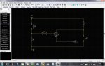
The PS2 has two mini joysticks, and I want them to be interchangeable in there functions. This means I need to be able to effectively swap two pairs of two wires around. This could be done with any 4PXT switch, but that would be ugly and more importantly, I can't find any at a reasonable price.

So is there any small solution to this. I've thought of using the ADC inputs and PWM outputs (with smooting caps) of a PICAXE. But the smallest chip that can do that is a 20X2, or a combo of other smaller chips. I currently have a few 08M's and a couple of 28X1's, but the 28X1 are too big, and I would need to use four 08M's.

Are there any other solution? I have two spare PTM tactile switches, which can control which way round the joysticks are switched.

Thanks in advance for any solutions.
David.
 

hippy

Ex-Staff (retired)
I suspect you really need a quad, 2-input analogue multiplexor chip. You could use a PICAXE as described but it seems like overkill, more expensive and probably won't give such good results.
 

BeanieBots

Moderator
As Hippy says, you need a quad, 2-input analogue multiplexor chip but I can't think of one with the exact requirements. It could be done with a couple of the good old faithful 4066's but that would be 2 chips and you'd still a PICAXE to control them making it 3 chips plus a few discretes.
 

alband

Senior Member
Just googled the 4066 and quad analogue multiplexers, and I'm a bit perlexed.

I'm not really sure how they all work. They all seem to consist four groups of I/O pins and then some control pins. The datasheets, of course, assume a basic level of knowledge, so don't go through it.

The 4066 has four switches, each with two I/O pins and a control. Does this mean it has basically got four, electrically operated push to make switches?

Two other examples I found:
http://www.onsemi.com/pub_link/Collateral/MC14551B-D.PDF
Seems to have four switches, each with three I/O and only one control pin. It also claims to be 4PDT, but I can't tell how.

http://pdf1.alldatasheet.com/datasheet-pdf/view/3519/MOTOROLA/MC14016BCL.html
Seems to be similar to the 4066; four switches, four control pins, 2 I/O each.

Can someone shed a bit of light on how these things work. The second one in particular, if it can be used as a 4PDT, it wounds ideal.
 

MPep

Senior Member
A 4066 has a 'switch' which needs to be enabled, the control gate. So yes one package does indeed have 4 'push to make' buttons.

The 4016 is similar to the 4066. Can't remember what the differences are. MAXIM also have various packages available.
Most notably, is the fact that they claim a lower 'on-resistance' than the standard 4066.
If you are only switching digital signals, then there are no problems. If analogue signals are switched, then the on resistance may become a factor.
 

BeanieBots

Moderator
The 4016 is lower spec (higher on resistance) version of the 4066.
As Mpep describes, it is four switches in one package. A 'high' on the control pin 'closes' the switch.
It will pass an analogue voltage so it's ideal for switching things like pots. The only caveat is that the switched voltage must be between 0v and it's supply rail voltage. Other than that, it behaves much like a relay does.

A (analogue) multiplexer is a collection of analogue swithes with their inputs all commoned on one input pin and internal logic controlled by 'address' lines. The behaviour is like a rotary switch. ie, the commoned end be used to select any one of the other 'inputs' or it can used to 'direct' a signal on that pin to any one of the 'outputs'.

Don't forget that an analogue switch (just like a relay) works in both directions so each 'contact' can be either input or output hence they are labelled I/O.

Hope that helps.
 

alband

Senior Member
From what I knew of multiplexers, I though they used a few number of pins to control lots of inputs using sort of binary logic. With three control pins, you could choose between 8 pins (000, 001, 010 etc).

So how come that MC14551B has only one control pin, and three pins devoted to each switch? At first I though that, this one pin must be a serial input that would allow the device to control each of the switches. This would also have meant that each switch could be double throw. However, there is no evidence of this on the datasheet. Also, at farnell, they list it as having 2 inputs and 8 outputs.

Does it indeed seem likely that a PICAXE is the best solution?
 

hippy

Ex-Staff (retired)
The MC14551B is a quad, two-input analogue multiplexor, so there's only a need for one input; it switches all four switches to one set of inputs when high, to the other set of inputs when low. It's exactly like a 4PDT switch.

A multiplexor will be much easier than a PICAXE.
 

alband

Senior Member
Ah, I see. Sounds perfect. I think I'll need to employ a thyristor to latch my spare PS2, PTM inputs to control the multiplexer.

Thanks for all the quick replies! Hopefully, I wont need to post again (for a while)...
 

BeanieBots

Moderator
I think I'll need to employ a thyristor to latch my spare PS2, PTM inputs to control the multiplexer.
Like Hippy, I was a little surprised at that comment.
Certainly not the most conventional way of latching inputs.
PLEASE post the circuit. I'm genuinely intrigued.
 

alband

Senior Member
Each joystick on the controller can be pressed down, to operate a PTM tactile switch.

I would use those to select which joystick would be the main stick.

Output of the thyristor goes to the 14551 control...

P.S. why do I get a feeling there is a much better way of doing this?
 

Attachments

BeanieBots

Moderator
That's perfectly OK as long as the 10k pullup provides sufficient current to keep the thyristor latched on. It's certainly a very small footprint solution.
 

alband

Senior Member
Right. I'll bare that in mind when testing it, and probably use some smaller values.

Can you suggest and reliable, small footprint thyristors?

Thanks for all this help as usual, especially since it isn't very PICAXE'y.
 

BeanieBots

Moderator
Can you suggest and reliable, small footprint thyristors?
Ha.Ha. ... and there's me thinking you'd found a suitable device.
I was about to ask you to post a link to the device you were going to use but I guess you've not found one.
I'm sure there is a nice little T092 packaged device out there that only needs a few mA hold current. Please post a link when you find it.
 

hippy

Ex-Staff (retired)
I'd have a think about what you are trying to do and how you want it to operate. The multiplexor requires a signal, high or low, to select / swap the two joystick positions over. The question is how to generate and control that signal.

You may want it to start with A / B then a push switches that to B / A and it stays that way until powered off, but do you want to be able to switch back without powering off ? Also, does the mechanism proposed interfere with gameplay and can it accidentally switch the joysticks during gameplay ?

I'd have chosen a small, discrete, switch which could be used directly, or with a flip-flop, to control the signal line and switch the joysticks over.
 

hippy

Ex-Staff (retired)
"Holding current" is the current which must be passing through the device ( A to K ) to keep it conducting. I'm not sure why that's listed as a "max" in the datasheet rather than a "min".

It's this effect which allows AC mains control of light dimmers etc - The gate is triggered, the triac conducts, the light comes on. As the mains hits zero crossover point, the voltage is zero, the current is zero, the holding current is below required, the triac stops conducting until another trigger pulse is supplied.

www.st.com/stonline/books/pdf/docs/3563.pdf
 
Last edited:

BeanieBots

Moderator
Good link Hippy. Explains it nicely.

I'm not sure why that's listed as a "max" in the datasheet rather than a "min".
Although it's the MINIMUM current which will keep the device latched on, the designer needs to know the MAXIMUM value that it will be for any given device.
 

hippy

Ex-Staff (retired)
Viewed form a designer's perspective I read BeanieBot's comment to be "it's the maximum you have to provide to guarantee expected operation, provide below and that it won't / might not work as expected".

It's convoluted way of describing it IMO, but I can understand the logic.

What it means in practice is that you must provide that current ( or more ) to keep the thyristor latched on.
 

alband

Senior Member
So, is the problem that; if this required minimum current, that must flow into the collector, is so low, the device will never de-latch, because there will always be at least this amount flowing into it?
 

hippy

Ex-Staff (retired)
It's more that you have to have a largish current flowing through the device to keep it conducting / latched, but also, if the current drops below that it will stop conducting / un-latch.

So if you have a switch and pull-up R to 5V, wish to replace the switch with a thyristor which has 100mA holding current, that R would need to be 50R for this to work. Any greater than 50R and current through the thyristor would be less than 100mA and not enough to keep it conducting once the gate trigger was removed.

This is a rough circuit of how a thryistor can be used as a latch. "Set" is push-to-make, normally open, "Reset" is push-to-break, normally closed. With AC rather than DC the latch will automatically reset itself as current drops to zero at mains crossover ...


Code:
5V >----.--------.------------
       .|.      .|.
       | |      | | 50R
       |_|      |_|
        |        |
        |        }-------------> High / Low signal
        |        |
     _| O       |O
Set |_|         |=== Reset
      | O       |O
        |       _|_
        |      _\./_
        |       /|
        `------' |
                 |
0V >-------------^------------
 

Jaguarjoe

Senior Member
So if you have a switch and pull-up R to 5V, wish to replace the switch with a thyristor which has 100mA holding current, that R would need to be 50R for this to work....


Code:
5V >----.--------.------------
       .|.      .|.
       | |      | | 50R
       |_|      |_|
        |        |
        |        }-------------> High / Low signal
        |        |
     _| O       |O
Set |_|         |=== Reset
      | O       |O
        |       _|_
        |      _\./_
        |       /|
        `------' |
                 |
0V >-------------^------------
Don't forget that the SCR needs about 1.5-2 volts to work so R now becomes 30 ohms or so.
 

hippy

Ex-Staff (retired)
Don't forget that the SCR needs about 1.5-2 volts to work so R now becomes 30 ohms or so.

Thanks; I hadn't realised that ( I've only worked with mains and thyristors / triacs where it wasn't really a lot of concern ).

I personally wouldn't consider a thyrsitor the most appropriate way of creating a high / low digital signal.
 

alband

Senior Member
What would have been your first thought?
Thyristors are the only way I know how to latch an output (other than PIC's).
 

BeanieBots

Moderator
Umm.... a latch ?

D-Type, J-K type.
Personally, I'd probably knock one up with a couple of gates.
Your thyristor designed latch might not be most peoples (including my own) first thought but it is a single 3-pin device solution.

Up to you if you want to persue that design. I see nothing wrong with it but you want a thyristor with the lowest holding current.

EDIT:
Your first proposed device is OK. (not perfect but OK).
The second device would be hopeless. For a start it needs 90mA to turn on so you'd need a driver.
(though it also says 2mA min to NOT turn on so you MIGHT get away with SOME devices)
Also, the 100mA latching current will be a nighmare to maintain.
 
Last edited:

alband

Senior Member
Didn't know latches actually existed, so I've done a bit of googling etc.

I reckon the "SR" Latch is just what I need. I couldn't find any cheep, small SR's, but I have just found the logic needed to make one. It just needs two NOR gates wired correctly.

So, I would plan to get this and wire it up like this. Attach each PTM to the S and R inputs (just treat them both as normal inputs and forget the "set" "reset" functionality), then attach the input of the multiplexor to one of the outputs.
 

westaust55

Moderator
Didn't know latches actually existed, so I've done a bit of googling etc.

I reckon the "SR" Latch is just what I need. I couldn't find any cheep, small SR's, but I have just found the logic needed to make one. It just needs two NOR gates wired correctly.
SR or RS Latches (part of a group of logic gates known as flip flops) abound
It depends how many you want etc.

Have a look at the 74LS279 by way opf example.
http://www.datasheetcatalog.org/datasheets/50/375560_DS.pdf

"Latches" are often also used on other chips such as the ubiquitous 74HC595 to latch the output data.

Maybe if you give a bit more information on what you are doing someone can point you at other existing chips rather than "build your own" from basic logic gates.
 

hippy

Ex-Staff (retired)
When constructing flip-flops and the like from discrete logic gates pay particular attention to input polarities, power-up states and when both Set and Reset are asserted simultaneously or overlap.

Some can have inconsistent power-up states, indeterminate states, both Q and /Q outputs asserted together or neither asserted, and some may even go into oscillation or give incorrect pulses and glitches.

All that can be designed or worked around, but it is something to be aware of for any particular application.
 

moxhamj

New Member
I need to catch up on where this thread has been; thyristers sounds a very strange solution. Check out the 4051 (my favourite analog multiplexer and demultiplexer), the 74HC74 and the 74HC76. Also 4PDT latching relays, particularly ones with 5V coils. And right at the beginning, a comment about a switch costing too much, which I don't quite understand, but I suspect I don't quite understand the question *grin*. Is the switching process controlled by something else, eg a micro, or does the user select it somehow, in which case, why not a physical switch?
 

alband

Senior Member
To be honest, isn't this going to be much easier to do with a trusty old PICAXE. I've got a few SMT 08M's around, they should do the job no problem. I can even change things if I want to afterwards. It would also be a lot smaller and could even do a bit of extra stuff if necessary.
 

moxhamj

New Member
I'm sure it will be easier with a picaxe.

There is one thing though that a picaxe can't do and that is switch analog voltages. I guess what it can do is sample the voltage then output a pwm out on another pin, and an 08M could do one of those, but it would be harder to do multiple lines. A picaxe paired with either 4066 or 4051 chips is a pretty nifty combination. Also, the 4016/4066/4051 type chips can switch signals in both directions. So a 4051 can take one analog input and switch to one of 8 analog outputs. But the same chip can listen to 8 analog inputs and switch one of those to an anaog output.

Or - a picaxe controlling a multi pole latching relay?
 

alband

Senior Member
A relay would be too big, so I agree it would be best to have an 08M control a multiplexer. However, I reckon I'll use the MC14551B because I need to switch 4 analogue paths with as smaller footprint as possible.

I still haven't got much space, so I'll need to knock up some designs to see if it all fits.
 

Wrenow

Senior Member
A picaxe may not be able to switch analoque voltages, and that is what the discussion is about, but I am wondering why you would want/need to here.

The more I ponder, if I understood correctly, the desire is to swap the jobs of the two joysticks.

I presume both joysticks are being read. If so, would it not be easier to, when switched, just swap which variable is used?

As in (very rough) pseudocode.

Main:
Read Left Joystick to w1
Read Right Joystick to w 2
if switch on
funct1=w1
funct2=w2
else
funct1=w2
funct2=w1
Do whatever else
goto Main

Cheers,

Wreno
 

alband

Senior Member
No quite like that.

I'm using the hardware of a PS2 controller (main focus on the joysticks) and the circuitry of a USB joystick (like, but not, this).

I need to be able to wire the four axis of the two joysticks to the four inputs of the USB joystick, but be able to switch them. So, the MC14551B does the actual switching, the PICAXE control the switching by providing a high or low to pin 9 of the MC14551B.

Another thought though, could the PICAXE power the MC14551B. Connecting the output of one of the pins directly to VDD (pin 16) of the MC14551B? Or would it need a driver?

This control would allow me to turn the joysticks on and off as well.
 

hippy

Ex-Staff (retired)
To be honest, isn't this going to be much easier to do with a trusty old PICAXE.
Depends on what part of "this". Creating a toggling flip-flop or latch, probably, but you've still got the routing of joystick control lines which will be best handled through analogue switches or similar.
 
Top