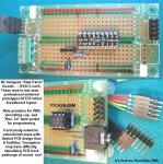
A virtual breadboard

manuka

Senior Member
Hosting such a goodie is indeed flattering, but approx. how large have things become!? I assume JavaScript is still the engine (it's inbuilt to FireFox & IE) ?

Thought re battery pak & switches- as these are always off board (typically in a 3xAA switched battery box), perhaps just a couple of supply leads be sketched to indicate this? 7 segs. are fun, but variations on orientation, side/bottom pinouts & CC/CA may produce headaches!

I've visions of Dr_A installing this on a PC for waiting room patients to amuse themselves with! Stan.
 
Last edited:

moxhamj

New Member
Don't laugh Stan, many of my patients have expressed gratitude that I have the latest issue of Silicon Chip in my waiting room. As well as the latest issues of New Scientist, Scientific American, Time and National Geographic. (all purged after 6 months or so) As well as the more standard fare such as Who magazine, and Women's Weekly. Even some UK publications as well like Country Living. Perhaps I should scatter some breadboards around as well...

Re hosting, would the original author be happy to host as we (ie westy) adds things?

I love the simplicity of this java script. It loads almost instantly. It needs no instructions. It looks like the real thing.

Manuka, back in the olden days, you could buy a physical PCB that happened to have the same layout as a breadboard. So once it was working, you could transfer the components and wires over one at a time to a real board. Do these still exist?
 

manuka

Senior Member
Aside from Westy's zeal, Ray himself has just uploaded some tweaks to his original VBB (sample below). These allow longer BBs, coloured & vertical LEDs, longer & flipped ICs, electrolytics & even red & black rails (rest easy Dippy- selectable!). Check it yourself => http://www.musicfromouterspace.com/ElectronicTools/virtualbreadboard/index.html

To avoid duplicated efforts I certainly hope Westy & Ray are keeping in touch with each other?

Those paxolin PCBs were/are still available via DSE Aust/NZ (part H-5605 ~US$2), but clever Kiwi Andrew has made a far superior quality fi-glass "Kiwi Board" version at much the same price. They're now widely used here in NZ, & MicroZed (the Aust. PICAXE agent) will be stocking them to support "SiChip" articles. Stan
 

Attachments

Last edited:

manuka

Senior Member
SS: Thanks-corrected! With longer VBBs now available, perhaps even a (wider) 40 pin DIP IC option may suit?
 

Attachments

Last edited:

westaust55

Moderator
Virtual Breadboard

Re hosting, would the original author be happy to host as we (ie westy) adds things?

I love the simplicity of this java script. It loads almost instantly. It needs no instructions. It looks like the real thing.
I have asked Ray, the orginal author, about sending back our work as a combined effort but while Ray was thankful for the offer, he indicates he wishes to go his way. His earlier request was only that we keep a link to his website (if possible) on the VBB screen.

The current total package size is around 2MB and slowly growing.
We may end up having to create a few zipped files and put on this forum.

Off to do a few other tasks. Hopefully an hour on more VBB changes this afternoon . . . .
 

moxhamj

New Member
I see Ray's board now has the option for marker pen!

Great to see there are multiple sources for those PCBs. And at good prices too.

Some thoughts. See this link here http://www.dse.com.au/cgi-bin/dse.storefront/4a20aa8810e4db6e273fc0a87e01070d/Product/View/H4044

This is a pretty standard board, but it makes mention of *8* bus bars, not 4. That is the same layout as my boards I bought 25 years ago - in other words the supply busses are split half way along. I wonder if the long red and black lines on the simulation might give the impression that the connection goes all the way along?

This actually got me the other day. I breadboarded up a circuit and it would not work. I had not installed a jumper for the ground half way along the bus bar, and half the components were not actually connected to ground.

So does the bigger board need this indicated in some way? Or are there different designs of breadboard out there?

Another thought - if red and black marker pen is allowed, would it be worth very faintly having the actual vertical and horizontal connections marked? Veteran users of breadboards can "see" these connections with the mind's eye, but to a newbie, a breadboard is just a sea of holes.

The coloured leds on Ray's board are great. Red, Yellow *and* Green. As an aside, I just got me some real blue and purple leds. Very pretty they are too. It took a bit of searching but I managed to get the blue ones with a blue colour in the resin as well as a wide viewing angle and a diffuser (rather than the more standard water clear, narrow viewing angle that blue seems to come in).
 
Last edited:

tarzan

Senior Member
Just one more request if it hasn’t been asked for already.
Two power rails top & bottom with magic marker colour coding.
This can allow for +V, 0V and i2c bus etc.
 

MartinM57

Moderator
Either versions look very impressive - a feature request for me would be the ability to put components vertically.

Connecting two adjacent holes with a vertical resistor is a simple thing to do in reality, and saves space and link wires, but with a fixed length resistor on VBB you need a rather circuitous (!) route, an extra link wire and you waste a line of holes.

No idea how the marking would work though - popup as you hovered over it showing the component in horizontal view (or even as if looking at the board sideways) ;)
 

westaust55

Moderator
Unfortunately Ray seemed to have little interest in my sending him info on what I have done.

This may result (unfortunately) in two gradually more diverging versions.

On my 19inch and 22in LCD monitos, breadboards could be longer still
and using Ray's them I can impliment this and the dual red/back tracks on both sides as mentioned above.

Between other task with family today I did impliment the rotating of all chips and making the "height:/thickness of green caps reduce slightly as the length reduces. The note tabs are also flippable as well now in my version.

Tracked down images for other components as well today. Electros and switches etc ready for later. Can permit radial and single ended electros if desired by the members here :confused:

Was showing a visitor where I got my starting point from and did notice that Ray has, as mentioned, above expanded his VBB in line with some comments from manuka and myself earlier.

Will be out all day tomorrow so little progress in generall will be made this long weekend (here in WA)
 

manuka

Senior Member
It's akin to the assorted LINUX flavours I guess, but in this case Westy seems the dynamo. I wonder if Ray has any reservations about using his actual scripts & .gifs however? Here's his most recent email to me-
Hi Stan

I thank you for the suggestions thus far and I think they have improved the app but my main thrust is analog synth design. I am going to leave the tweaking and focusing for the picaxe world to the people whose main thrust is picaxe design. They have my permission to take the app to the next level needed to support picaxe education. I would appreciate if you would send me a URL to the improved app once people have made their changes so I can see it and link to it as well.

Cheers and good luck - Ray
Dr_A- that supply rail break has fooled many. Mmm-since BB enhancements themselves have now arisen, perhaps options for "magic markers" & doubled/broken supply rails may be worthwhile?

WestAust55: Just 2 Megs looks easy- but do I recall you saying 46 files at one stage? If I hosted them they'd be under a URL such as => www.picaxe.orconhosting.net.nz/vbb.htm , but it may be more realistic to offer the lot as JavaScript download for local off line browser use. Naturally add versions relating to "plug ins" etc that arise.

THOUGHT: It's just possible that Rev.Ed may be interested in this - are you there Hippy?
 
Last edited:

hippy

Technical Support
Staff member
The technicalities of hosting it would probably make it impractical for a project which is evolving and would likely introduce support issues which would be undesirable. I've personally found that publishing software on-line or for download is best done from web sites or FTP servers over which the developer has full access to and control over. As a HTML / JavaScript / .GIF project it should be suitable for hosting by any free web space provider and there are sites which support free hosting of downloadable projects.
 

Technical

Technical Support
Staff member
As hippy says whilst people are developing the project out of personal interest and the product is evolving it is probably better for them to work on their own server space, particularly when sharing code and developing in parallel.

However we think that this could be an excellent free tool, particularly for our educational market. So when a stable/fully featured version is finished we would be quite happy to support/maintain the project and host it on our server. We would also like to support a 'zip file' install because many schools run this type of application locally on their internal servers.

Our request! A single button screen capture to GIF/PNG.
 

manuka

Senior Member
Hippy/Tec: This is indeed good news that VBB finds favour, & that Rev.Ed may consider "final version" hosting.
In many ways, & I guess I speak for others, it's fitting that your loyal user base can give something back as thanks for the PICAXE phenomena! Stan

Extra: The latest from Ray himself mentions -
I think VBB is an excellent name and yes you can use the images and scripts and you can distribute the code as well.
 
Last edited:

westaust55

Moderator
some variance is :rolleyes: already creeping in. For example:

1. Have treated the rotation of LED's in the same sequence as diodes and other components in 90 degree increments.

2. Using a subscript means (_1 and _2) for images for DIP IC's, etc which allowed me to "compute the correct image for pin 1 down versus pin1 up from a single line of code.

I am also considering having all capcitors (poly/green, electro - radial + single ended, tantalum) under a single menu structure that would leave more room at the bottom for other items such as terminal blocks, switches and other 2-terminal devices.

I will go back and add in some of Rays new work for breadboards. I had already created an even longer BB until I found the 38hole limit for 1280 wide screen resolution. 1440 and 1680 wide resolutions open up a new field but need to keep the fundamentals in mind as well.
 

BCJKiwi

Senior Member
Moving the components table from the LHS to above or below the BB itself would allow another 5 rows to fit on the 1280 wide screen. Would also give a bit more flexibility to accommodate additional component types, larger circuits, and larger chips.

Addendum

The images of the board seem pretty large on screen. Have an 18" LCD screen where the current 'standard' is 19" (4:3 aspect ratio).
At 1280 res across, the VBB is twice the width of a real BB - i.e. on screen measure is 5mm or .2" pitch compared to the real thing at 2.5 or .1" pitch.

While big is good for ease of use, wonder if part of the solution to longer boards and more components/larger ICs is to reduce the number of pixels in the graphics? The wires on the jumpers appear to be 6 pixels thick with the insulated sections 8 pixels thick. So while there isn't scope to halve the size of the images, reasonable compression could be in order. The standard BBs I have are around 60 columns wide so a 2/3 sized image set (or number of pixels per image) should get a regular size BB onto a 1280 screen width if the the board itself is the full width of the screen.
 
Last edited:

SilentScreamer

Senior Member
I personally like the width, it fits very nicely on my 17" 4:3 monitor at 1280X1024. I think having two breadboards one above the other could be useful for larger circuits rather than adding extra width.
 

hippy

Technical Support
Staff member
Bear in mind that a number of students will have NetBooks with small screens operating in fairly low resolution ( 800 x 600 ). Rather force a 'one-size fits all' option, allowing the user to select board size would be preferable.
 

SilentScreamer

Senior Member
The current smallest board does not fit on a 800x600 resolution (I just checked). From my school 1024x756 common for almost every PC, the newer PCs use 1280x1024. We do have a few that run on 800x600 (maybe 30-40 in the entire school) but nobody ever uses them as by the time they have logged in, most of the lesson has already gone by.
 

manuka

Senior Member
SS: I've not heard that " still waiting to log in" excuse for some years, but it certainly WAS common a decade back, with 10-15 min delays typical to get a room full of dead PCs singing & dancing. Mains overloads were common too, with rolling starts often required to stop fuse blowing on surges. We used to allow 200W a desktop, so 30 demanded 6kW ( ~25 Amps on 230V)

Anyway-let's face it- 1024 x 768 has been a regular screen standard for some years, although (as Hippy rightly points out) 7" netbooks need every pixel going.

Overdoing VBB may well be an issue, as at heart it's just a colourful display program for simple circuitry. We don't have rocket science designs in mind do we ? Come in Dippy!? Stan
 
Last edited:

SilentScreamer

Senior Member
SS: I've not heard that " still waiting to log in" excuse for some yearsn
Computer designed for 98 + Vista = trouble :p

Though Vista is only installed on one of them, the rest have XP and used to be acceptable but since the school got the Conflicker virus the school's servers are continually crashing even though they've removed it, even the newer Core2Duos struggle at times.

The problem that I find with 7" notebooks is that nothing fits on the screen, most modern software is design for a screen resolution of 1024x756 if not higher.
 

moxhamj

New Member
You can always add a scroll bar(s) for bigger boards.

I like the idea that it boots up at the small board. Then you add some simple components. If you run out of space, sure, go for the bigger board. But many of Manuka's inspirational picaxe articles in Silicon Chip have fitted on the smaller board.

Technical's suggestion of a single "click to save gif/png/jpg" button solves many problems of smaller screens. A brilliant suggestion! Work on a screen on any size on any browser, scroll if you have to to fit on your screen. But when it is all working, just 'click to save' and you know it is all there.

I'd love to see this hosted by RevEd with, at the very least, a simple library of the 08M and other beginner picaxes along with enough components to make a flashing led etc. I think we have already seen an 08M with the pins labelled. That really makes it so much easier for a beginner to get something working with picaxe.

I can also envisage a series of simple screen shots of some of the 'standard' circuits that are in the manual. Maybe these could even find their way into the manual, alongside the existing schematics? Schematics seem so simple to people who know how to read them, but to a beginner, there are so many potential sources of confusion. Eg the 'leg vs pin' problem. But a picture of a breadboard - anyone can copy that and get a circuit working.
 
Last edited:

westaust55

Moderator
VBB with single selector for multiple capacitor types

Okay folks,

Not much done today as out and about with family & friends while the weather was fine here.

Done a bit tonight and attached are two concepts for incorporating 4 type of capacitors into a single icon with either:
(a) a pull down menu for type, or
(b) a set of radio buttons with small images (for greencap, radial electro, RB type electro, and tantalum) over the buttons

Personnal I prefer (b) but lets see what the forum in general think. Won't affect the coding (still to be done)
Thinking to change the menu caps picture at left of screen to a composite pic to reflect the multiple types.

For the single sided RB type) electro's the placed image will be a circular image looking like the top side of the electro

Recognise that the greencaps are not polarity conscious but the cap schematic type images imply polority. Maybe able to look into changing as the type is modified . . . . (later)


@Dr_A,
yes i have PICAXE style chips with the basic pin ID's shown.
Yet to complete pin ID's for rotated types but the logic is fully functional for all DIP type IC's.
 

Attachments

Last edited:

Andrew Cowan

Senior Member
Definitly the pictures and radiobuttons. I've never heard of a greencap (non UK?), so I think the pictures are best. Any student can understand them.

A
 

hippy

Technical Support
Staff member
How does VBB work ? I would have expected it to be working with transparent GIF overlays but the reason I ask is that I see nothing ( very little ) with my FF and IE configuration which is to ignore what colours a page specifies and force my own ( white on black ). Normally GIF's still work fine ( except where mistaken presumption leads to using a transparent colour and expecting white as the background ), but in this case there are no colours at all, breadboard and components are invisible.

That would be something nice to fix to save me having to change my settings to use VBB and then back again.

When using physical breadboard I tend to use it with tracks horizontal, rather than vertical as it has been so far. Having that option also reduces the limits on number of tracks related to screen width / resolution, as it's simply scroll up and down can be as long as you want it.

Also, as well as a breadboard background, it would make sense to support a vero-board / strip-board background and a means to place track breaks - that's an obvioius progression which people are likely to ask for. An easy option is to just show the breadboard as vero-board with holes pre-cut where the breadboard tracks break, no options to add cuts. Just a different background image.
 

westaust55

Moderator
VBB image concept

Except for wires and resistors for which images are calculated and drawing on the fly, all other items are gif images. They do include a transparent colour to fill areas around the image of the component within the rectangular gif image.

Breadboards could include alternatives such as vero and similar protoboards later. It is just a case of having a board image and using maths to define where the holes are located.

At the moment the aim is to get an increased range of components constructed for the PICAXE community.
 

hippy

Technical Support
Staff member
Ok, as it is GIF based I'll have a look to see if I can find why they are not visible.

One other desirable minor tweak - configurable 2.2K or 2K2 selection conventions. I also tend to see US use of 0.1uF where the UK would use 100nF. It should be possible to store user configuration in a Cookie, along with last circuit edited.
 

westaust55

Moderator
Ok, as it is GIF based I'll have a look to see if I can find why they are not visible.

One other desirable minor tweak - configurable 2.2K or 2K2 selection conventions. I also tend to see US use of 0.1uF where the UK would use 100nF. It should be possible to store user configuration in a Cookie, along with last circuit edited.
Capacitor values are user entered into a field in the dropdown menu when a component is right clicked.
Look at the unnamed filed at the top of cap dropdown in post 67

Resistor values are a predefined list with value in ohms (1.5MOhm stored as 1500000) and the user visible value (1.5M)

wrt UK and US versions of component values, its like imperial and metric to me, I work interchangeably with both. Have even been know :eek: to say a piece of timer is 4 x 50 as in 4" x 2" (= 100mm x 50mm) :rolleyes:
 

westaust55

Moderator
I hope this doesn't end in tears with each one leap-frogging the other and any mutual relationship breaking down :(
At least in the short terms, I will go back and add Ray's updates into my version for selectable breadboards and some other tweaks, bt not necesaryily immediately. Will require some cut and paste as I already have extensive code mods for new features I have added.
 

manuka

Senior Member
WestAust55- those capacitors are gorgeous! Did you have any luck with pigtailed resistors ( & white LEDs!) however? In response to Dr-A's " sea of holes" comment, maybe some very faint "silk screening" could be added to each group of 5 holes as a visual aid? See => http://www.picaxe.orconhosting.net.nz/kiwacan.jpg - Andrew's Kiwi Boards have similar.

Re board size- I make a special effort to get my SiChip circuits onto the standard 23 column BBs, as these are educational standards,cheaply available & match DSE/Kiwi Boards hole for hole.

Mmm-time we gave VBB some hosting space for download trials? Suggest version 1.0 be added? Stan
 
Last edited:

boriz

Senior Member
“I will go back and add Ray's updates into my version”

Westy. I don’t know what communication you have had with Ray, but please don’t try to take his creation and run without implicit permission. You are obviously not without talent in the programming department. But let’s not forget that this was originally not your idea and not your program. I can appreciate everything you are doing, and it’s all good stuff, but I think code revisions should be submitted to the original author. “free for non-commercial use” Is cool. To be encouraged, not exploited.

Please accept my apologies if I am out of line.
 

manuka

Senior Member
Boriz: Good point & one I was wary about. However WestAust55, Dr_A & myself have all been in frequent contact with Ray the originator (refer my earlier posted quotes), & he's given repeated OKs for PICAXEers to run with his ideas/plunder his scripts/grab his graphics. Rather than "cease & desist" it looks more ( as we'd say downunder) a "mate- go for it" situation.

You couldn't ask for better -he confesses to having analog. synth. ears rather than breadboard eyes ! Stan
 
Last edited:

Mycroft2152

Senior Member
Boriz,

That's very sage advice. Let's put in perspective. You write a minor addition to Windows and want Bill Gates to include it in and associate your name with Windows.

I understand that Ray is open about others using his program and that's great. But as has been said Ray is more interested in the analog synth area.

This really makes Ray's program bloatware for PICAXE users.

Now that Westy undertands the functionality of the program, it is time to make it his own and re-engineer it for PICAXE users. Stripping out the simulation functions woould make it much more manageable and much smaller for downloads.

Just my 2 cents..

Myc
 

manuka

Senior Member
Mycroft2152: "Bloatware? Stripping out the simulation functions " ?? Westy's VBB is display only, & ~2MB! Stan
 
Last edited:
Top