24lc256 eeprom & picaxe 20x2

billacj

Member
I could use some help with my code to write and read to a 24LC256 EEPROM. I've successfully intregrated I2C for a DS1307 RTC, HMC6352 and analog LM34 outputting to a 2X16 LCD for a nifty time/temp/compass heading console so the 24LC256 should be a piece of cake but nooo, not yet.

Using the following simple routine to learn to use the 24LC256, it reads the LM34 or a fixed number, writes it to the EEPROM, reads the EEPROM contents back and using DEBUG everything displays on the PICAXE editor. However, reading the EEPROM gets FF in b8 & b9 as the result. The 24LC256 documentation says FF will be returned if the command is not successful.

I've looked at other code examples/tutorials/forum postings that were not specific to this EEPROM and tried many variations of the following code initializing the EEPROM FAST, Slow, byte and word. the EEPROM address is %1010000 so I've also tried setting the R/W bit in the address word for example 10100000 for write and 10100001 for read, no luck.

My goal is to learn to use the EEPROM to store my clock/temperature and heading just for the learning experience.

20X2, 5V operation, 4.7k pullup resistors on SCL/SDA pins on a proto board. Other I2C devices are removed from the board.

Wonder if I can get some help. Thanks Bill

20X2 with LM34 and 24LC256 EEPROM
Code:
	init:
	let adcsetup = %0000000000100000 	;set B.3 or ADC5 for LM34
	
	hi2csetup i2cmaster, %11000000, i2cslow, i2cbyte   ;Init PICAXE for 24lc256	
		
	main:
		b0=0
		b1=0
		  
		readadc10 b.3,w0 		;read LM34 value
		debug				;b0 reflects LM34 value(s)
		pause 1000
		  
		W1 = $0000		;eeprom mem addr 0000
		
		hi2cout w1,(b0,b1)	;write LM34 w0 to eeprom
		pause 20
		debug 
		pause 1000
		 
		b8=0			
		b9=0
		 
		hi2cin w1,(b8,b9)		;read from eeprom mem addr 0000 
		pause 20
		sertxd("Temp=", b8,b9,13,10)
		debug
		pause 2500
		;OBSERVE FF in b8 and b9 and LM34 output is OK in b0  
	goto main
 

nick12ab

Senior Member
You have the address set to % 11000000 in the code and not % 10100000 like the EEPROM requires.

Also, the non-B series of 24LC eeproms (24LC128, 24LC256 and any others without a 'B' on the end) use a word address and not a byte address. Your setup command uses i2cbyte.
 
Last edited:

billacj

Member
Arrrgh, thanks a million, BIG TYPO on my side. Here is my code for a simple program to share with others.
Read LM34, Write LM34 contents to 24LC256 EEPROM memory location 0000 or contents of W1, Read EEPROM location 0000 and debug display everything. EEPROM WP pin 7 to VSS, Address pins A0 A1 A2 low. Attach RTC and Compass to create a data logger.

init:
let adcsetup = %0000000000100000 ;set B.3 or ADC5 for the LM34

hi2csetup i2cmaster, %10100000, i2cslow, i2cword ;Setup 24LC256

main:
b0=0
b1=0

readadc10 b.3,w0 ;read LM34 value
debug ;b0 reflects LM34 value(s)
pause 1000

W1 = $0000 ;eeprom mem addr 0000 or make a random choice in W1

hi2cout w1,(b0) ;write LM34 w0 to eeprom
pause 20
debug
pause 1000

b8=0
b9=0

hi2cin w1,(b8) ;read from eeprom mem addr in W1 contents
pause 20
sertxd("Temp=", b8,"",b9,13,10) ;patch and use terminal for display
debug
pause 2500
goto main
 

garylcamp

New Member
I2C info

Where did you get the I2C info to interface to the PICAXE? In the manual, it refers to i2c tutorial but no search on the PICAXE site turns up any such document. In fact a search for i2c turns up no hits in the forum and at the bottom of the forum page, a "most searched for" tag only turns up your question and 2 others.

I love the PICAXE but the website and documentation kind of sucks (hit or miss info, poor cross ref. not kept very up to date).

P.S. I found the PDF under All Datasheets even though the "search" could not find it using the identical title.
 
Last edited:

jtcurneal

Senior Member
Check the Rev-Ed web site for the document axe110_i2c.pdf. It covers setting up a picaxe for using I2C to communicate with several devices.

Joel
 

hippy

Technical Support
Staff member
It's also available from within Programming Editor ...

Help -> PICAXE 18 datasheets -> I2C Tutorial
 

billacj

Member
Where did you get the I2C info to interface to the PICAXE? In the manual, it refers to i2c tutorial but no search on the PICAXE site turns up any such document. In fact a search for i2c turns up no hits in the forum and at the bottom of the forum page, a "most searched for" tag only turns up your question and 2 others.

I love the PICAXE but the website and documentation kind of sucks (hit or miss info, poor cross ref. not kept very up to date).
I found code for other chips in both C and BASIC that helped but reading the specs for the I2C chip is necessary to understand the addressing and the functions. The code affects the external chip as much as the PICAXE, the addressing and commands are for the external chip. PICAXE does a good job communicating with the external chips once the hi2csetup, hi2cout and/or hi2cin commands are properly formatted. Each external I2C chip has small differences but once you get the hi2csetup correct I2C is very easy to use. Study my code listed above for the 24lc256 EEPROM. By the way there are other eeproms but the addressing and read might be different. Also be mindful that a 32k eeprom is not addressed like 1,2,3,4 ..... to 32k, for some reason the 24lc256 is R/W in 64 byte blocks so every 64 addresses the bank address must be incremented by one. count 1 to 64, increment bank address from zero to one, count 1 to 64, increment the base address by one, etc .... Don't forget to use WORD variables for addressing .... its pretty funny but when I first started I overlooked this tiny but important item.
 

billacj

Member
Ooops, I forgot to mention the I2C tutorial uses older slave, read & write I2C commands. Study and use the newer I2C commands hi2csetup, hi2cout, hi2cin. EAsy, fast, reliable. Bill
 

billacj

Member
Here is real code to write to the 24lc256. Put this into a loop and increment the address and or storage variable. I2cslow should be i2cfast but thats ok for now, it works fine with a 20X2. ADDRESS with Word Variables. I have working code for a DS1307 RTC and HMC6352 Compass chip too. Next I'm working on making a I2C interface to a standard LCD readout. Bill

hi2csetup i2cmaster, %10100000,i2cslow,i2cword
pause 10 ;optional delay time
debug ;to check whats happening
hi2cout final_address,(b1) ;save raw Minutes
pause 10 ;recommended write delay time
debug

Here are lines of code to read the 24lc256, again you can put this into your own loop to increment the address and variables.

geteeprom:
hi2csetup i2cmaster, %10100000,i2cslow,i2cword
pause 10
debug
hi2cin final_address,(b1)
pause 10
debug
 

inglewoodpete

Senior Member
With X1 and X2 PICAXEs, apart from exceptional circumstances, you should only need to issue the Hi2cSetup command once in a program.

When accessing each i2c slave with X1/X2 PICAXEs, use the command option that includes the address of the peripheral:
Code:
     Hi2cIn [slave_addr],location,(variable,...)    'Template
     Hi2cOut [slave_addr],location,(variable,...)   'Template
     '
     'Examples:
     Hi2cIn [80], final_address,(b1)
     Hi2cOut [97], minutes,(b2)
 

billacj

Member
I'm using 3 I2C devices on the buss, a compass chip, Real Time Clock and 24lc256 eeprom. If I understand your comment, I can put the hi2csetup command for each chip in the INIT: paragraph to run once at program start and then use your example when selecting the individual I2C device in the run code? Tnx ... Bill


With X1 and X2 PICAXEs, apart from exceptional circumstances, you should only need to issue the Hi2cSetup command once in a program.

When accessing each i2c slave with X1/X2 PICAXEs, use the command option that includes the address of the peripheral:
Code:
     Hi2cIn [slave_addr],location,(variable,...)    'Template
     Hi2cOut [slave_addr],location,(variable,...)   'Template
     '
     'Examples:
     Hi2cIn [80], final_address,(b1)
     Hi2cOut [97], minutes,(b2)
 

inglewoodpete

Senior Member
I'm using 3 I2C devices on the buss, a compass chip, Real Time Clock and 24lc256 eeprom. If I understand your comment, I can put the hi2csetup command for each chip in the INIT: paragraph to run once at program start and then use your example when selecting the individual I2C device in the run code? Tnx ... Bill
Almost correct. You only need the Hi2cSetup command to configure the PICAXE's i2c pins for i2c working. Addressing each i2c peripheral is done via the Hi2cIn or Hi2cOut command.
 

westaust55

Moderator
To further expand upon the comment by IWP,
You can only have One i2c setup command active.
If you enter several consecutively, then only the last setup configuration will be used.
While using devices of the same type then as IWP states just add the device slave address within the I2C I/O commands.
However if you change to a different device needing a configuration change such as between byte and word address length then you need to issue a new i2c setup command.
 

bigjoe

New Member
Here is real code to write to the 24lc256. Put this into a loop and increment the address and or storage variable. I2cslow should be i2cfast but thats ok for now, it works fine with a 20X2. ADDRESS with Word Variables. I have working code for a DS1307 RTC and HMC6352 Compass chip too. Next I'm working on making a I2C interface to a standard LCD readout. Bill

hi2csetup i2cmaster, %10100000,i2cslow,i2cword
pause 10 ;optional delay time
debug ;to check whats happening
hi2cout final_address,(b1) ;save raw Minutes
pause 10 ;recommended write delay time
debug

Here are lines of code to read the 24lc256, again you can put this into your own loop to increment the address and variables.

geteeprom:
hi2csetup i2cmaster, %10100000,i2cslow,i2cword
pause 10
debug
hi2cin final_address,(b1)
pause 10
debug
I am trying to do something like what BILLACJ did .... a solid state data logger using 24LC256 .... my difference is I am using the PICAXE-40X1

I can not get the 24LC256 to accept the hi2cin it seems that it never gets programmed and I am stuck. I am using custom hardware and I have checked it several times for an error. I have no trouble using a DS1307 and I can successfully write to the DS1307's CMOS RAM. I copied Bill's code and it still does not work for me. On the 22LC256, pins 1,2,3 and 4 are grounded, pin 7 is tied high.

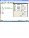
Screenshot of the code and debug window is attached.

Joe
PICKAXE24LC256.JPG
 

westaust55

Moderator
You would in future do better to post you actual code in text format rather than in image format.
Also there is no need to reply with quote (with the button at bottom right), just use reply to thread using the button at the bottom left of the forum pages

The fact that are receiving a value of 255 into byte variable b8 suggests a hardware error.
From your comments: Pin 7 which is the WP and must be pulled low to ground, not high.
Have you read the Rev Ed i2c tutorial document: http://www.rev-ed.co.uk/docs/axe110_i2c.pdf


EDIT: maybe also have a look at this datasheet as well:http://www.rev-ed.co.uk/docs/axe111.pdf
 
Last edited:

billacj

Member
To further expand upon the comment by IWP,
You can only have One i2c setup command active.
If you enter several consecutively, then only the last setup configuration will be used.
While using devices of the same type then as IWP states just add the device slave address within the I2C I/O commands.
However if you change to a different device needing a configuration change such as between byte and word address length then you need to issue a new i2c setup command.
Here are the hi2c setup commands (picaxe 20x2) for the DS1307 RTC, 24LC256 EEPROM and HMC6352 compass chip if anyone needs an example. The eeprom and 6352, not the DS1307, could be changed to i2cfast_8. The read and write code are already listed in this thread. $42 is the same as %01000010 .

DS1307 RTC hi2csetup i2cmaster, %11010000, i2cslow_8, i2cbyte
24lc256 EEPROM hi2csetup i2cmaster, %10100000,i2cslow_8,i2cword
HMC6352 hi2csetup i2cmaster, $42, i2cslow_8, i2cbyte

Billacj
 

westaust55

Moderator
If you use a DS1338Z-33 in lieu of the DS1307, this albeit surface mount SOIC8 outline is functionally equivalent down to the battery back-up and 56 bytes of NV RAM but has the advantages of working at 400 kHz (so i2cfast parameter can be used) and a wider voltage range.

Note that to be technically correct, if you have just one slow i2c device on the network then the i2cslow command should be used for all comms not just the slow device otherwise the slower device may be “confused” when other devices are communicating and itself try to send a response corrupting the data.
 

billacj

Member
If you use a DS1338Z-33 in lieu of the DS1307, this albeit surface mount SOIC8 outline is functionally equivalent down to the battery back-up and 56 bytes of NV RAM but has the advantages of working at 400 kHz (so i2cfast parameter can be used) and a wider voltage range.

Note that to be technically correct, if you have just one slow i2c device on the network then the i2cslow command should be used for all comms not just the slow device otherwise the slower device may be “confused” when other devices are communicating and itself try to send a response corrupting the data.
Correct, the appropriate hi2csetup resides in my code sections for RTC, Compass and EEPROM. I chose to run 'slow' while developing the code (20X2 8mHz) . The high accuracy RTC on my desk, forgot the part number, includes an accurate temperature sensor. Extra RAM is also available on the RTC and compass but I can't quote now because I'm away from my desk. I am currently using a LM34 analog temperature sensor and will switch to the sensor on the new RTC. Anyway, I've completed a neat console for my old VW pop top, the console include date,time, temperature sensor, compass direction and eeprom to capture data of the last 15 hours. All but the 2X16 display and LM34 are I2C. Next project is to use one of the PICAXE as a I2C interface to a standard parallel LCD display.

Very good discussion. Thanks .... Billacj
 

bigjoe

New Member
Thanks all

I have now changed wiring on the 24LC256 pin-7 to ground, but it still does not work for me.

Software: I copied and pasted Bill's code.
Hardware: custom, ten 8-pin sockets, the first eight are wired for 24LC256, with pins 1,2 and 3 counting 0 to 7 binary for A0, A1 and A2. Pin-7 is now grounded and pin-8 is +5V. Checked that I2C SDA and I2C SCL are wired correctly with each having a 4.7 K pull-up. The ninth socket is wired for a DS1307.

Compiles, Loads and Runs; but, all I get back is $FF $FF

I can write and read from the DS1307 with no problem; also to the DC1307's CMOS RAM.

Joe
 

billacj

Member
Can we see your code ? Keep your test circuit simple, PICAXE and eeprom, remove the others. ground eeprom A0, A1, A2 and enable write protect per an earlier posting. The chip select address in the HI2CSETUP (AO) command does not change, it stays A0 for read or write. Check the speed of your MPU to make sure I2C is running either 100 or 400khz, I am running a 20x2 at 8mhz, other chips might need different values in the hi2csetup to compensate. Also, run hi2csetup for the eeprom followed by hi2cread for the eeprom. leave the recommended pause 10 between commands to allow time for the chip to write.

Are you using WORD variables for the address? Byte variables only count to 255.

geteeprom:
hi2csetup i2cmaster, %10100000,i2cslow,i2cword
pause 10
debug
hi2cin final_address,(b1)
pause 10
debug

Billacj, time to go play ham radio, will check back later.
 

westaust55

Moderator
$FF suggests that no data is being returned. That could be either software or hardware related.

Are the EEPROMS installed when you have tested successfully with the DS1307 RTC?

We are guessing without more information as please:

1. Post your complete program code as Billacj has suggested already
2. Post your schematic for the circuit
3. Consider uploading some clear photos of the entire circuit so we can trace the conenctions between chips. Folks have spotted construction errors this way in the past.
 
Last edited:

billacj

Member
I just thought of one more item to check, make sure there are only one (1) set of pull up resistors. The reason I mention this is that when the chip is added to a shield board, the manufacture might have included the smd pullups so in fact there could be multiple pullups in the clock and data lines.

Something I have no information on is the maximum length of the clock and data busses, I suppose they should less than inches long to prevent signal deterioration. When I was a large scale systems tech I could see the affects of cable capacitance on overly long cable runs, high speed digital square wave forms would round out and the peak signal would be less than optimum due to cable DC resistance and reactance not to mention the long lines are good radio antennas for noise. The faster the data rate, the more profound the effect of cable length on the signal. This was my personal argument to run the I2C buss slow, cause I didn't know about I2C buss characteristics.

If any of you are design engineers, could you comment on my last statement regarding I2C buss length. Thanks .... Billacj
 

bigjoe

New Member
Hi and thanks all ... I will try to fill all requests so you can help me. First on the software ... I did a copy and paste of billacj software as I assumed that it ran; but the only difference I have is a custom board and a PICAXE 40X1. I have tried several versions of the software. I am going to try to post a general I2CTest.Bas ... this does well with the DS1307, but I get no response from the 24LC256. Also, I am not all that sure how to use this reply ... hope I posted the code correctly. Would it be better to post the code as an attachment so it would be easier to paste into the Compiler/Editor?

Now I am going to try to post the custom PWB layout as a .jpg file

Let me know if you really want the schematic as it is rather busy


'PICAXE -40X1 Register & variable Allocation and initialization ****************
'
'w0 reserved, just incase I need a 32 bit accumilator.
'b0 reserved
'b1 reserved
'w1 reserved
'b2 reserved
'b3 reserved
'w2 reserved
b4 = $00 'used by fractions of a second, 1/100. DS1307 needs BCD format.
b5 = $30 'used by seconds, counts to $60 and rolls over.
'w3 reserved
b6 = $59 'used by minutes, counts to $60 and rolls over.
b7 = $11 'used by hours, counts to $24 and rolls over. Set bit 6 to ZERO for 24hour format.
'w4 reserved
b8 = $01 'used by day as a name, like Friday=6, an enumeration counts to 7 and rolls.
b9 = $0f 'used by date as a number day of the month, counts to $
'w5 reserved
b10 = $08 'used by month of year, counts to $
b11 = $0b 'used by year
'w6
b12 = %00010000 'used by control to turn on Square Wave at 1 HZ
'b13 = 0
'w7 reserved
b14 = %11010000 'used by realclockaddress, %1101000x
'b15
'w8 'used by addressoffset, for the DS1307 there is no address offset.
'b16 = %00000000 'used as a shutdown command for the DS1307
'b17
'w9
b18= %10100000 'used by externalmemoryaddress
'b19
'w10
'b20
'b21
' ................
'w12
'b24
'b25
'w13
'b26
'b27
'end of PICAXE-40X1 register variables.

'PICAXE Symbols and Equates, variable name assignment ************************
symbol fractions = b4
symbol seconds = b5
symbol minutes = b6
symbol hour = b7
symbol day = b8
symbol date = b9
symbol month = b10
symbol year = b11
symbol control = b12 'controls the output square wave on DS1307 pin6.
symbol addressoffset = w8 'used by addressoffset, for the DS1307 there is no address offset. Offset is a word.
symbol realclockaddress = b14 'I2C address for the DS1307
symbol externalmemoryaddress = b18 'I2C base address for the 24LC256
'symbol shutdown1307 = b16
symbol counter = w9
'symbol count1 = b18
'symbol count2 = b19
'
'reserved symbols: hi2clast, hi2cflag, @ptr, @ptrinc, @ptrdec, hserflag and hserptr are also used.
'
'Start of code **********************************************************************

init: 'initialization module.
hi2csetup i2cmaster, realclockaddress, i2cslow, i2cbyte 'set up for a DS1307 RTC.
hi2cout [realclockaddress], addressoffset, (seconds,minutes,hour,day,date,month,year,control) 'only want this to run once.
pause 1000
for b2 = 8 to 63 ;test for the CMOS RAM in the 1307.
addressoffset = b2
hi2cout [realclockaddress], addressoffset, (b2)
pause 10
next b2
hi2csetup i2cmaster, %10100000, i2cslow, i2cword '24LC256 without the B sufix uses word addressing.
debug
pause 1000
addressoffset = 0
for b2 = 0 to 47
hi2cout [externalmemoryaddress], addressoffset, (b2) 'put something in the 24LC256 to read later.
pause 10
next b2
hi2cout [%10100010], addressoffset, ("This is to chip 001")
pause 10
'wanted to put something in each 24LC256, but this is commented out as it does not work.
'hi2cout [%10100100], addressoffset, ("This is to chip 002")
'pause 10
'hi2cout [%10100110], addressoffset, ("This is to chip 003")
'pause 10
'hi2cout [%10101000], addressoffset, ("This is to chip 004")
'pause 10
'hi2cout [%10101010], addressoffset, ("This is to chip 005")
'pause 10
'hi2cout [%10101010], addressoffset, ("This is to chip 006")
'pause 10
'hi2cout [%10101110], addressoffset, ("This is to chip 007")
'pause 10

main: 'main module. Endless loop.
debug
hi2csetup i2cmaster, realclockaddress, i2cslow, i2cbyte 'set up for a DS1307 RTC, again.
pause 1000
addressoffset = 0
hi2cin [realclockaddress], addressoffset, (seconds,minutes,hour,day,date,month,year)
debug 'DIAGNOSTIC only, remove if this code is to be part of larger program
for b2 = 8 to 63
addressoffset = b2
hi2cin [realclockaddress], b2, (w8)
pause 10
debug 'DIAGNOSTIC only, remove if this code is to be part of larger program
next b2

'goto main
'*************************************************************************
'work in progress, the 24LC256 do not respond
hi2csetup i2cmaster, externalmemoryaddress, i2cslow, i2cword '24LC256 without the B sufix the 24LC256 uses word addressing
pause 1000
for b17 = 0 to 20
hi2cin [externalmemoryaddress], b17, (b19)
pause 1000
hi2cin [%10100100], b2, (b20)
pause 10
hi2cin [%10100110], b2, (b21)
pause 10
hi2cin [%10101000], b2, (b22)
pause 10
hi2cin [%10101010], b2, (b23)
pause 10
hi2cin [%10101100], b2, (b24)
pause 10
hi2cin [%10101110], b2, (b25)
pause 10
debug 'DIAGNOSTIC only, remove if this code is to be part of larger program
next b17
goto main
 

bigjoe

New Member
Thanks Joel

I went to the URL that you posted .... I can not monitor the I2C bus, but I did check that SCL and SDA were wired correctly, they were my prime suspects. I have the bus speed set as slow in software. The data length has to change back and forth for different I2C device on the bus. I have the data length for the 24LC256 is set at a word. I have the address offset for the 24LC256 set as a word. I have eight 24LC256 and one DS1307 on the I2C bus. The communication with the DS1307 works correctly. With the 24LC256 all I get is a $FFFF reply. My guess is that I am never getting any data written to the 24LC256. My Vcc is regulated. My I2C bus pull-up are 4.7K. My I2C bus master is the PICAXE-40X1. My custom board is small, about the size of a credit card and all the PWB trace lengths are short.
 

bigjoe

New Member
I am trying to post an image of my PWB. The PWB is the size of a credit card and has lots on it. I am trying to make it 4X so it is easier to see. I did the layout with ExpressPCB.

U14 is the PICKAXE-40X1
U4 to U11 are the 24LC256 chips
U12 is the DS1307
R6 and R7 are the 4.7K pull-ups

Joe

PICAXEH.JPG
 

billacj

Member
I believe I see the problem, first, use word variable for the eeprom memory address, next for all eeproms you are using the same hi2csetup and chip select address, the hi2csetup chip select address is unique to the chip and to the hi2cin / hi2cout so for each chip there must be a unique hi2csetup and hi2cin/out using the correct chip select address. Also, I can't confirm that your hi2cout/hi2cin memory address format is correct, you have (base variable,offset variable), I can't find anything in the manuals that show this format. I increment my memory location in a word variable then use the word variable in the hi2cin/out to address the eeprom location. I suggest you remove all but one eeprom at 10100000 and get it to work. Anyway the hi2csetup and hi2cin/out is the problem. Billacj

'PICAXE -40X1 Register & variable Allocation and initialization ****************

hi2csetup i2cmaster, %10100000, i2cslow, i2cword '24LC256 without the B sufix uses word addressing.
debug
pause 1000
addressoffset = 0
for b2 = 0 to 47
hi2cout [externalmemoryaddress], addressoffset, (b2) 'put something in the 24LC256 to read later.
pause 10
next b2
hi2cout [%10100010], addressoffset, ("This is to chip 001")
pause 10
'wanted to put something in each 24LC256, but this is commented out as it does not work.
'hi2cout [%10100100], addressoffset, ("This is to chip 002")
'pause 10
'hi2cout [%10100110], addressoffset, ("This is to chip 003")
'pause 10
'hi2cout [%10101000], addressoffset, ("This is to chip 004")
'pause 10
'hi2cout [%10101010], addressoffset, ("This is to chip 005")
'pause 10
'hi2cout [%10101010], addressoffset, ("This is to chip 006")
'pause 10
'hi2cout [%10101110], addressoffset, ("This is to chip 007")
'pause 10
 

westaust55

Moderator
The information by Billajc is not entirely correct.

Yes, the address length parameter neets to be i2cword to address more than 255 bytes in each EEPROM chip

There only needs to be one Hi2csetup command for multiple EEPROM.
The HI2COUT command sytax is:
HI2COUT [newslave], location, (variable,...)​
The newslave paramter enables you to select another memory chip without the need for a new setup command line

The "addressoffset" parameter as used by bigjoe is just the EEPROM address location parameter. Effectively a location offset relative to memory location 0 in each chip.


Can I suggest that you start somewhat smaller and try to test with a single EEPROM installed.
And try writing just one byte at a time then read it back and see if you get the value written to the EEPROM.
Then see what happens.
 
Last edited:

bigjoe

New Member
Thanks westaust55

I chopped out the DS1307 code and removed the DS1307 chip. I chopped all the statements of allocations and assigning of symbols. I think that I have to write and read words rather than bytes. Anyway the code should now just write forty-eight words/bytes to the first 24LC256 and then try to read it. It still fails, all I get back is $FFFF.

The code for this test is:

'PICAXE -40X1 Register & variable Allocation and initialization ****************
'
'**********************************************************************

init: 'initialization module.
hi2csetup i2cmaster, %10100000, i2cslow, i2cword '24LC256 without the B sufix uses word addressing.
pause 1000
for b2 = 0 to 47
hi2cout [%10100000], b2, (b2) 'put something in the 24LC256 to read later.
pause 10
next b2
'hi2cout [%10100010], addressoffset, ("This is to chip 001")
'pause 10
'wanted to put something in each 24LC256, but this is commented out as it does not work.
'hi2cout [%10100100], addressoffset, ("This is to chip 002")
'pause 10
'hi2cout [%10100110], addressoffset, ("This is to chip 003")
'pause 10
'hi2cout [%10101000], addressoffset, ("This is to chip 004")
'pause 10
'hi2cout [%10101010], addressoffset, ("This is to chip 005")
'pause 10
'hi2cout [%10101010], addressoffset, ("This is to chip 006")
'pause 10
'hi2cout [%10101110], addressoffset, ("This is to chip 007")
'pause 10

main: 'main module. Endless loop.

'*************************************************************************
'work in progress, the 24LC256 do not respond
'hi2csetup i2cmaster, externalmemoryaddress, i2cslow, i2cword '24LC256 without the B sufix the 24LC256 uses word addressing
'pause 1000
for b17 = 0 to 47
hi2cin [%10100000], b17, (b19)
pause 10
hi2cin [%10100100], b17, (b20)
pause 10
hi2cin [%10100110], b17, (b21)
pause 10
hi2cin [%10101000], b17, (b22)
pause 10
hi2cin [%10101010], b17, (b23)
pause 10
hi2cin [%10101100], b17, (b24)
pause 10
hi2cin [%10101110], b17, (b25)
pause 10
debug 'DIAGNOSTIC only, remove if this code is to be part of larger program
next b17
goto main


Maybe the 24LC256 needs something that I am not giving it?

Joe
 

hippy

Technical Support
Staff member
As westaust55 suggests, try something very simple ...

Code:
#Picaxe 20X2
#Terminal 9600
Pause 2000
SerTxd( "Reset", CR, LF )
HI2cSetup I2CMASTER, %10100000, I2CSLOW, I2CWORD
Pause 1000
HI2cOut 0, ( 123 ) 
Do
  Pause 1000
  HI2cIn 0, ( b0 )
  SerTxd( "Read ", #b0, CR, LF )
Loop
 

Armp

Senior Member
Check that the SDA and SCL lines are wired correctly. Looks from the PCB that pin 5 SDA on the 24LC256 could be connected to pin 6 SCL on the RTC, and vice versa?
 
Last edited:

bigjoe

New Member
As westaust55 suggests, try something very simple ...

Code:
#Picaxe 20X2
#Terminal 9600
Pause 2000
SerTxd( "Reset", CR, LF )
HI2cSetup I2CMASTER, %10100000, I2CSLOW, I2CWORD
Pause 1000
HI2cOut 0, ( 123 ) 
Do
  Pause 1000
  HI2cIn 0, ( b0 )
  SerTxd( "Read ", #b0, CR, LF )
Loop
Thanks Hippy ... but this is not even close to what I can try. I am doing a Picaxe 40X1. And I favor debug rather than setting up a terminal. But I will give the rest a try.

Joe
 

bigjoe

New Member
Check that the SDA and SCL lines are wired correctly. Looks from the PCB that pin 5 SDA on the 24LC256 could be connected to pin 6 SCL on the RTC, and vice versa?
Thanks Amp .... I will check this again, the SDA and SCL lines being wired wrong are a prime candidate for the problem ....

Joe
 

westaust55

Moderator
@ bigjoe,

Again also I suggest that you post your schematic diagram.
In particular if it is the input to the program that created your PWB layout it will be far easier for folks to "read" and follow through for incorrect connection.

As a comment on forum etiquette, when posting more than a couple of lines of program code, please use the [code] and [/code] markers around your program code as per the sticky Read Me First thread at the top of the forum so that it your code appears in a sub-window as per hippy’s code example above.
 

hippy

Technical Support
Staff member
Thanks Hippy ... but this is not even close to what I can try. I am doing a Picaxe 40X1. And I favor debug rather than setting up a terminal. But I will give the rest a try.
I assumed it was a 20X2 from the thread title. For 40X1 you only have to change the #PICAXE and #TERMINAL setting ...

Code:
[b]#Picaxe 40X1
#Terminal 4800[/b]
Pause 2000
SerTxd( "Reset", CR, LF )
HI2cSetup I2CMASTER, %10100000, I2CSLOW, I2CWORD
Pause 1000
HI2cOut 0, ( 123 ) 
Do
  Pause 1000
  HI2cIn 0, ( b0 )
  SerTxd( "Read ", #b0, CR, LF )
Loop
 

bigjoe

New Member
Sorry for all the goofs in protocol, I am just finding my way around on the forum.

Hippy, I posted in the 20X thread because I had a 24LC256 problem just like billacj did. However; I am using a PICAXE-40X1; 4Mhz resonator on a custom board. All I wanted was a solid state data logger with time-stamp like Bill was doing and it wanted it small as I could go without using surface mount components.

westaust55, I could not find the button that put the code things around the program. I will type them in next time.

I did not post a schematic because I could not figure out how. The schematic has problems as I drew it on a E size sheet and it wants to be reduced to an A size sheet to be exported. I can either attach the original graphic file or post a screen shot/.jpg. The screen-shot is no good, one can not read anything unless one zooms in and then one can not see the whole schematic at once.

Armp, I think you are right ... I have an wiring error on the SCL and SDA lines going to the 24LC256. I thought that I had checked this twice, but I messed up.

So if anyone still wants the schematic ... I am open to suggestions as to how to post it. On the layout; I do have a screen-shot/jpg of the layout at X4 if anyone wants it. The PWB is crowded, I have 13 chips in a credit card size space with 12 of them DIPs; with one a 40-pin DIP also a a 50-pin connector.

Joe
 

TAMeyer

Member
Posting Schematics / Code Tags

Joe:

If PCB Express does not offer a "print to file" option, a couple of alternatives exist.

1/Under the Program Editor download is a link for a PDF print driver.

http://www.rev-ed.co.uk/picaxe/software.htm

Install that and print your schematic to a PDF file.

2/Alternately you can use one of dozens of screen capture programs. Once you have the image(s), reassemble them in Paint, Gimp or other graphic program, and "Save As" a JPG.


======================


For code tags select "Go Advanced" when replying (see attached #1). This will spawn a window with additional options. Select the "#" button (see attached #2)
Advanced.jpgCode.jpg
Your cursor will then be placed between the two tags. If your code is already on the clipboard, then Ctrl-V.

Lastly use, "Preview Post" in the lower right before submission.

Good luck.

T
 
Last edited:
Top