There are a number of threads on this forum regarding development systems.
This is a teaching system. Its for teaching basic circuits and Picaxe programming not developing a project or application.
Its offered simply as a starting point for teachers.
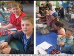
To give context its aimed at students who attend University of the Third Age (U3A). These students are retirees. The course has zero budget; this may change in the future but at present I'm recycling what I have.
The course is structured around "How Does a Washing Machine Work" as a focus question, so we'll look at LED's (the display), switches, buzzers, thermisters (water temperature control), LDRs (to measure water turbidity) and motor control. The course goes for an hour a week for 8 weeks.
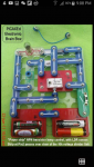
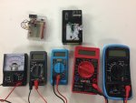
The photos show how I've set it up.
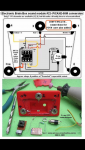
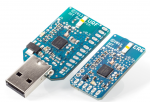
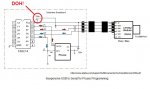
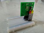
Its based on a breadboard that is bridged in the middle with a 18pin socket. Links between the socket pins and a female header join the two halves of the breadboard. The Picaxe 08m2 pcb shown mounted in the header has the programming resistors and supply decoupling capacitors. The board uses the socket as a bus that brings out the power supply and pins c.0 to c.4. It has a diode to protect against reverse supply connection.
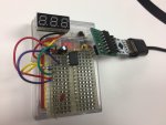
Each device used has its own bus made of male pc headers. The first photo shows the LED board. My students need only match the right hand side pins and the board is correctly wired to power, c.1 and c.2. This minimizes errors due to failing eyesight but for those that can, the circuit can still be traced out. Using c.2 also allows me to introduce pwm.
The bridging socket allows breadboard space to use multiple device boards, for example using an LDR to control the lights.
I used pins c.0, c.1 and c.2 for output devices and c.3 and c.4 for inputs with the exception of the motor board.
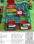
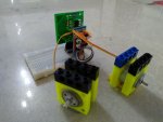
The second photo shows my motor setup. I'm using MX1508 motor controllers to drive two 4.5V motors. These are used with my kids/grandkids lego to make a simple robot. Again, the connecting matrix board has a bus made of male pcb pins that match the Picaxe board. The MX1508 uses pins c.0, c.1,c.2 and c.4. It leaves c.3 for a switchable input.
Its a real limitation. The current solution is to use a second picaxe board connected via a serial connection. The main advantage is that I have the boards.
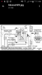
However I'll build another set of Picaxe boards using a 20m2 based on a design by @lbenson. It should be possible to bring out port C to a bus so that it matches the 08m2 port C so I can reuse my existing device boards.
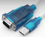
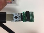
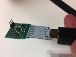
Finally I cut off the axe027 audio jack and soldered the wires to the same bus as the picaxe board. Again, by lining up the right hand side pins, the correct connections are made.
Cheers.
This is a teaching system. Its for teaching basic circuits and Picaxe programming not developing a project or application.
Its offered simply as a starting point for teachers.
To give context its aimed at students who attend University of the Third Age (U3A). These students are retirees. The course has zero budget; this may change in the future but at present I'm recycling what I have.
The course is structured around "How Does a Washing Machine Work" as a focus question, so we'll look at LED's (the display), switches, buzzers, thermisters (water temperature control), LDRs (to measure water turbidity) and motor control. The course goes for an hour a week for 8 weeks.
The photos show how I've set it up.
Its based on a breadboard that is bridged in the middle with a 18pin socket. Links between the socket pins and a female header join the two halves of the breadboard. The Picaxe 08m2 pcb shown mounted in the header has the programming resistors and supply decoupling capacitors. The board uses the socket as a bus that brings out the power supply and pins c.0 to c.4. It has a diode to protect against reverse supply connection.
Each device used has its own bus made of male pc headers. The first photo shows the LED board. My students need only match the right hand side pins and the board is correctly wired to power, c.1 and c.2. This minimizes errors due to failing eyesight but for those that can, the circuit can still be traced out. Using c.2 also allows me to introduce pwm.
The bridging socket allows breadboard space to use multiple device boards, for example using an LDR to control the lights.
I used pins c.0, c.1 and c.2 for output devices and c.3 and c.4 for inputs with the exception of the motor board.
The second photo shows my motor setup. I'm using MX1508 motor controllers to drive two 4.5V motors. These are used with my kids/grandkids lego to make a simple robot. Again, the connecting matrix board has a bus made of male pcb pins that match the Picaxe board. The MX1508 uses pins c.0, c.1,c.2 and c.4. It leaves c.3 for a switchable input.
Its a real limitation. The current solution is to use a second picaxe board connected via a serial connection. The main advantage is that I have the boards.
However I'll build another set of Picaxe boards using a 20m2 based on a design by @lbenson. It should be possible to bring out port C to a bus so that it matches the 08m2 port C so I can reuse my existing device boards.
Finally I cut off the axe027 audio jack and soldered the wires to the same bus as the picaxe board. Again, by lining up the right hand side pins, the correct connections are made.
Cheers.
Attachments
-
 135.4 KB Views: 36
 -
 137.3 KB Views: 35
 -
 115.6 KB Views: 35
")