20x2 LCD - (leaving 7-seg LED display)

manie

Senior Member
I have purchased the LCD serial firmware driver and the RTC upgrade chip etc.
Which would you go for, the 16x2 or the 20x2 LCD ??
The 20x2 LCD datasheet link just drops the 16x2 datasheet in your lap. I remember reading somewhere (forum ??) that the axe's only like 16x2 not 20x2. Is this so ?

If there is extra room for more characters, I'm sure life will dictate that it is just not enough !!

Manie
 

manie

Senior Member
EC: Any suggestions as to what/where ? There are so many, if I can, I'd like to save as much as poss on shipping/postage. There is always a minimum oreder amount on other sites. Thanks
Manie
 

kevrus

New Member
Ive always had good LCDs at reasonable prices from Sure Electronics in China...via e-bay...quick delivery to the UK as well, the only thing I look out for is to make sure the LCD uses the HD44780 driver. I have picked up a large 20x4 display which has 9mm high characters...good for easy viewing.
 

hippy

Ex-Staff (retired)
As kevrus says, LCD's with genuine Hitachi HD44780 drivers are a good choice and should work with the AXE033. Others may be "compatible" but use different drivers, they should work but if not, unlike controlling an LCD direct from a PICAXE, there is not a lot of scope for tweaking initialisation sequences.

The more characters and lines on a display the more flexible it be in what you can display. As you go smaller you have to get more ingenious with what and how you display things. If you are not sure how large you need, you could buy a large one and use that for development, buy a more suitable one for a particular project when you have all the display issues sorted out using the big display.
 

manie

Senior Member
Eclectic:
From your 1st link:
Sorry for ignorance but what does this all mean ? Can I use the firmware chip with this ?
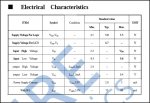
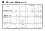
Display mode - STN,Positive
Driving method 1/16 duty, 1/5 bias
Manie
 

eclectic

Moderator
From my point of view, a very nice looking piece of kit.
(And with HD44780 driver)

I own a similar screen, with a PHAnderson controller.
Just a few points.

1. It needs the backlight on ALL the time.
Make sure you've got a hefty power supply.
And the correct high power resistor.

2. Do not directly solder.
Use pins / sockets/ ribbon cable to connect to your main board.

I'm sure there will be more advice / opinions shortly.

e
 
Last edited:

kevrus

New Member
Ive used those, or something very similiar from Sure...as Eclectic says, the backlight needs to be on all the time that the display is read so the PSU needs to be capable of handling the extra current.

Again, as Eclectic says, use PCB headers/sockets fo the connections. I have a couple of LCDs with PCB plug and socket for testing and then use header pins for a finished job with my own piggyback daughter PCB.

I have had quite good success with reducing the backlight current (increasing the series resistor) and still having good viewing illumination so some experimentation here may pay dividends.
 

manie

Senior Member
Thanks guys, that looks OK then. As you say HD chip so firmware will work also and 20x4.I'll look further and decide tonight, depends on shipping cost now....
Manie
 

hippy

Ex-Staff (retired)
If they hadn't 'splatted' the datasheet's data with a banner it would be easier to say. The thing I look for these days is whether Vcontrast needs to be negative, couldn't tell. If the backlight is 250mA and needs to be always on it's something I'd pass on. Where I've used backlights I tend to keep the current down well below that, a warm glow but giving good contrast and better viewing.

There are probably thousands of LCD's out there which are possibilities. Price looks good, so probably worth taking a gamble on if it appeals to you.
 

kevrus

New Member
The backlight could always be switched off in between viewing..from memory, i'm running one at approx 30mA (or thereabouts) and get good illumination.

Hippy's point about the 'negative' voltage for the contrast is worth noting. As an aside, graphic LCD displays tend to require this although some (not sure how many) have an on-board negative voltage generator (if generator is the right word).

For a good visible display, look out for monochrome OLED displays. I have a couple of these from e-bay and they have no backlight but are extremely visible as they appear similiar to an LED display, current draw is very low...only found them in 16x2 and 20x2 formats though.
 

eclectic

Moderator
FWIW, I've just taken out the blue 4 x 20 display,
from my PHAnderson board. (Max rec. backlight = 200mA)

Wired it to a FRM010 serial LCD controller.

Tried different resistors and measured the currents.

Well lit room - 40mA is plenty. 10 mA is perfectly adequate.

Dimmed the lights, 10mA is great.

And then, as Kev says, switch it off when you're not using it.

e
 
Last edited:

manie

Senior Member
Well it was HELLLLLLL !!!!! Signing up on chep-bay.... I've bid, one bid = mine, ends in 2hours, and WOW ! shipping is FREE ! to S.A. !!!! Can't believe it. Thanks for the pointers guys...

Yeah, I also thought I'd just add backlight resistance and slow it down some, I've got portc pins spare, so I can switch it off also....

Manie
 

moxhamj

New Member
These are a nice display. I bought a batch of 5 not long ago. Code is the same as for a 16x2 with a slight tweak to get the other two lines. Re the backlight - I just ran it with a 1k resistor which would be about 5mA or less and it seems more than bright enough.
 

manie

Senior Member
These are a nice display. I bought a batch of 5 not long ago. Code is the same as for a 16x2 with a slight tweak to get the other two lines.
Dr.A: Pray tell more on the other two lines, I'll be using the RevEd firmware as serial driver.. Thanks in advance
Manie
 

eclectic

Moderator
Manie.
Until the Doc gives more specific advice, you can play with this.

Code:
main:

serout 1,n2400,(254,1)
pause 500

serout 1,n2400,(254,128,"128")

serout 1,n2400,(254,192,"192")

serout 1,n2400,(254,148,"148")

serout 1,n2400,(254,212,"212")
It works on both of my 4 x 20, and also works in the simulator.

There's a good explanation of the serial 254... style codes
in the AXE033 datasheet, which you can get from the Editor.
(Pages 8 - 9)

e
 

Attachments

Last edited:

manie

Senior Member
sbscott: Thanks, had a look at it, I will probably end up doing RS232 at 1200bd or so and don't need a fast speed on the system really. So slow speed is ok. Thanks.
 

westaust55

Moderator
Dr.A: Pray tell more on the other two lines, I'll be using the RevEd firmware as serial driver.. Thanks in advance
Manie
@Manie,
typical 4x20 displays electrically only have 2 lines.
Line 1 is folded over and continues as line 3
Line 2 is folded over and continues as line 4

That is why the example code eclectic gave you to play with has values of 128, 192, 148 and 212 to point to the start of each line.

Your program has to keep track of where the characters will next be displayed
 

moxhamj

New Member
Sorry, posted that and then had to sleep. Yes, as eclectic and westaust55 have said, the instruction 128,192,148 and 212 move the cursor to each of the 4 lines.

Those 20x4 LCDs are parallel, not serial. But just wire them up as per the picaxe manual #3, on pages 30 onwards. There is the code a few pages down. Just use that. This is the instruction list from the manual and you just send these numbers to the wrins code. Add 148 and 212 to that list for the other 2 lines.

1 Clear display and move to the start of the first line
2 Move the cursor and display ‘window’ to the start of the first line
4 Set ‘right to left printing’ mode
5 Set ‘scroll printing to the left’ mode
6 Set ‘left to right printing’ mode
7 Set ‘scroll printing to the right’ mode
10 Turn visual LCD screen off
12 Hide cursor
13 Make cursor flash
14 Turn visual LCD screen (and cursor) on
16 Move cursor left one position
20 Move cursor right one position
24 Scroll display ‘window’ left one position
28 Scroll display ‘window’ right one position
128 Move cursor to the start of the first line
192 Move cursor to the start of the second line
 

manie

Senior Member
That should get me going... parallel ? Hmmmmmm ? A new direction to ponder again.. do I need the firmware for it then ? I've bought TWO of them, do I now need different LCD modules for this serial firmware ? Will oggle the manual and see... thanks guys.
Manie
 

hippy

Ex-Staff (retired)
I can't quite follow the latest posts but most LCD's are parallel interface so you can either wire them direct to a PICAXE using multiple control lines or use a serial to parallel converter such as the AXE033 or the FRM010 chip and use a single serial line.

If you've got a parallel LCD and an AXE033/FRM010 you are probably okay, you can communicate with the AXE033/FRM010 from a PICAXE using SEROUT. No need for any extra firmware.
 

manie

Senior Member
Thanks Hippy, you are right off course, I forgot what I read about the firmware driving LCD at 4 bits if I'm not mistaken. So yeah, disregard my rather dumb question above. It will work and only occupy 1 pin on the Picaxe.
Manie
 

moxhamj

New Member
Re "It will work and only occupy 1 pin on the Picaxe."

Could you pls clarify that a bit more? Parallel uses more than one pin. The manual describes how to wire it up, and in a practical sense, you would want an 18X or bigger. Like Hippy says, most displays are parallel. I've only ever used parallel displays, and one thing that is great is the code is pretty much the same for an 8x2 or a 16x2 or a 20x4 or even bigger displays. Parallel is also cheaper because the display does not need a serial to parallel converter.

One thing about parallel displays is they have 16 pins in a single row. I've not been able to find an IDC single row connection system, so I ended up getting a whole lot of little boards made that turn 16x1 into 8x2 pins. This is a standard IDC header and it is polarised as well so you can't destroy a display. This http://drvernacula.topcities.com/n8vem.htm has a photo of one one the left, connected to some rainbow cable and there is an IDC socket at each end of cable. I've now got a variety of picaxe and CP/M and other boards all with a "standard" 8x2 box header. I've also got a whole range of LCD displays of different sizes, and it is possible to plug them in and out of the circuit depending on how many lines are needed etc.

This helps debugging a huge amount, as I've had a few dodgy LCD displays (almost certainly due to wiring them up incorrectly).

On this page http://drvernacula.topcities.com/home_automation_wireless_project.htm , if you scroll down about 6 pictures, there is a more detailed picture of the adaptor board and a closeup of the header. A couple of pictures further down is a closeup of an OLED display. OLED displays look absolutely gorgeous - they are crystal clear, you can read them from any angle and you can read them from the other side of the room. They use hardly any more current than an LCD and only cost a bit more. They are pin-for-pin compatible with standard LCD displays and, as far as I know, they are much more readily available in parallel.
 

manie

Senior Member
DR. A: Yes LCd's are parallel devices, however, the RevEd Firmware chip does the work for you acting as the convertor. Your Picaxe will connect with Pic chip Firmware in Serial and talk via RS232. Thus only one pin on the Picaxe is used. The Firmware will "translate" to parallel and drive the LCD. I think I read (datasheet ??) that the firmware does this in 4-bit mode, one extra chip yes but the Picaxe saves on outputs used. Haven't studied the Firmware datasheet yet, just glanced through it, but it has some capabilities pre-programmed that cuts down on code size in the Picaxe. I've purchased two and will give it a try when the blue LCD arrives.

Experts: Am I correct in the above ?
Manie

manie
 

hippy

Ex-Staff (retired)
@ manie : Yes, you are right. I think Dr_A missed the bit where you mentioned you were using them with FRM010 interfaces.

@ Dr_Acula : I think you missed the bit where manie mentioned using them with FRM010 interfaces :)
 

manie

Senior Member
The FRM010's etc. have landed in S.A. today, the Blue 20x4 LCD's from Sure Electronics are on their way, so far so good, will let you know the next time I run into a problem:rolleyes::D

Manie
 

moxhamj

New Member
Yes, I missed the bit about using them with FRM010 interfaces *grin*.

I've also got some 20x4s on the way from Sure Electronics.

I'd be interested in your thoughts the costs etc eg FRM010 is another chip but it saves pins on a picaxe so you can use a smaller picaxe chip, and probably will free up some code space too.
 

kevrus

New Member
I find that the FRM010 is quite reasonably priced, but then I do live in the UK so P&P isn't an issue, and as stated, it only uses one picaxe pin.

I use my own piggy-back board to mount on the back of the LCD hence there is no issue regarding the need to include an extra chip on any project boards. Making a few piggy-back boards means there will always be one at hand.
 

manie

Senior Member
K: hich is exactly what I'm doing also. The dispaly/ keyboard is a separate unit hardwired for RS232 comms to the main board. See my post on "multiple interrupts".
Manie
 
Top