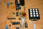
Starting to work with the Blue 20x4 LCD. Made the "Keyboard/Display" PCB Saturday afternoon (1 1/2 hrs-drilling included). It has its own power regulators with BD244C's as Pass transistors for higher current (6 Amp) should I need it. I include these Pass Transistors on my PSU now as standard. I soldered in a machine pin 28-dip socket for the 28x1, the Picaxe pins does not like that, so before I damaged the 28x1 pins I put it in a "normal" socket and piggy-backed that into the machine pin socket. The 2x16 header on the left is for the LCD, the 2x8 on the right is for the keyboard feeding the analogue voltage to the PicAxe adc pin 3. I've used a few 0.0R(wire link) "resistors" as jumpers. It makes layout of traces easier and sure looks neater than actual wire jumpers. The brown spot at right is a proper mistake ! I dried the board on a 60watt bulb and left it too long ! Fortunately the PCB was not damaged.
The backlight on the Blue LCD (ex Sure) is switched on/off with a miniature toggle on the case front, this passes 5V through a 270R limiting resistor. This gives a current of 19mA and the backlight is quite bright.
This board will have two way RS232 comms with the Main Controller, for alarm set points etc. and to display the current temperature readings etc. locally in the Chook-House. The Main controller also transmits the data via the Polygon 433 MHz transcievers to the study in the house. Alarm set points can be varied from there as well.
In assembling and testing the analogue "one-wire" keypad I found the data for the Rev-ED keypad to be incorrect with the pinouts as shown.
See the page here:
http://194.201.138.187/epages/Store.storefront/?ObjectPath=/Shops/Store.TechSupplies/Products/SEN040
Row 4 and Row 2 has been swapped ! See the picture with wires swapped over correctly. After swapping the wires around the analogue voltages fell neatly in place. I could pick this up from the analogue voltage table I produced. Technical, please have a look at the data displayed on the page above...
The LCD/433MHz/RS232/40x1-controller is comming together well now.
Thank you ALL for assistance that got me this far, it is really appreciated.
I wonder if I should start a new thread to continue the now combined pieces as the "integrated" project with various separate boards ? If "yes", then a name suggestion is in order...
Manie
Edit:
The black "silk screen" markings on the board is something new I'm trying. It worked very well in fact, UNTIL I started "cleaning up" to get it "better".... I will get it right and tell you what I did.