Hi,
5) b) I think of a multi-line (rows count) display and colums characters enough after splitting the ASCII table in two parts.
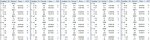
I'm not sure what you mean by "ASCII Table" but if you mean the "Tabular" (Table) display of the Slave Addresses of the program, then I considered that a "Gimmick" (I don't know if that will translate) , which I nearly removed. IMHO all that is needed for a simple custom "tester" is to display a Slave Address (or two), a few "Error" Codes (or numbers) and perhaps a "Name" / Type Number of the Slave. There are only 112 available Slave Addresses, so (as we have already found), some are allocated to multiple (different) devices, particularly since I2C Memories often use 8 adjacent addresses.
I didn't respond to your earlier comments, but personally, for a "User Interface", I believe in the "Keep It SimpleS" philosophy. I would NOT add any (toggle) switches, but just use the PICaxe to change any "configuration" options, e.g the (weak) pull-up resistors on/off and supply voltage/pins, etc.). Maybe just a (few) low-cost pushbutton(s) input, which can be easily "debounced" by the software, if necessary. The "header" in the "ASCII Art" of that program was mainly intended to show how 6 contacts along the edge of a Solderless Breadboard could be used (with one of the larger PICaxes) to test many configurations of Breakout board.
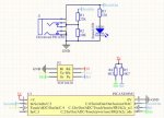
For a dedicated hardware "tester" one might include a (e.g. 14-pin) "Zero Insertion Force" (ZIF) IC socket, arranged with most permutations of the 4 pins, but the KISS solution is just 4 pins and a short "Dupont" M/F ribbon cable, which could accept ANY sequence and spacing of header pins. Note that since I2C is basically an "Idle High" system, the Vcc of the DUT (Device Under Test) could be connected (unconditionally) to the supply rail and just the Earth (e.g. from pin c.4 of an 08M2) used to protect/switch/modulate the Earth connection to a lower voltage (e.g. 3.3v) DUT.
5) ... The ssd1306 oled display(has sda, scl for I2C but maybe serial variant exist) could be the solution for the I2Cscanner of AllyCat(Alan) and
@PhilHornby mentioned in this thread on post #20-22 :
Yes, I considered the SSD1306 and one of my (many) projects "On the Back Burner" is an 08M2/SSD1306 emulation of the AXE133/4 (maybe even towards the AXE033). The bit-mapped display maps quite well to a "1602" (8x16 pixels ASCII font) or "2004" (6 pixels wide characters), using "Double Height" characters for the 128 x 64 pix version. Most of the "font" coding is already done and documented
HERE , but I still need to finalise the HSERIN input code, to support the much more intensive (complex) and slower (bit-mapped) display driver.
The problem with an I2C display (on a single bus) is that it can't report any of the "Bus Faults", because the bus must be working correctly. However, for this project, it would be possible to use the "Bit Banged" I2C code from post #1 of my Code Snippet thread on "different" pins, leaving the (embedded hardware) I2C bus to drive the SSD1306 as quickly as required. A "larger" PICaxe would be better, but it might just fit onto an 08M2: Pin C.4 could be the SDA(2) line. In most cases the SCL doesn't need to have a Tri-State capability (which is only required for "Clock-Stretching" devices) so the C.0 (Serout) pin probably could be used for SCL(2). Pin C.0 does actually have a Weak Pullup and Tri-State capability, but that's definitely straying away from the KISS principle.
")
Cheers, Alan.