inglewoodpete
Senior Member
I found this LCD-Keypad Shield while browsing the Deal Extreme website. The price AU$8.50/US$8.99/EU8.05 includes free shipping - great value if you're prepared to wait the 20-30 day delivery time. For under 9 dollars, I was prepared to take the risk and have not been disappointed.
Hardware
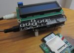
The LCD Keypad Shield (DealExtreme SKU 118059) has a blue backlit LCD with built-in N/S/E/W/Select(& Reset) keys in a small keypad. It is 100% compatible with the PICAXE AXE401 Shield: just a matter of plugging it into the AXE401, develop and download some driver software and play!
The LCD uses the 4-bit parallel interface to a Hitachi HD44780 compatible driver chip. The backlight is wired to accept PWM, allowing software control of the illumination and, consequently, power drain. So the unit uses 4 data, 2 control & 1 pwm output pins from the 28X2.
The keypad uses a resistor ladder, so key presses are decoded using an ADC channel. The values are steady, so only 8-bit ADC is required.
The contrast is controlled by the (blue) multi-turn pot located in the top left of the photos. The backlight LED can be seen at the right of the display screen. The trusty PICAXE AXE401 shield can be seen, almost hiding, under the LCD/Keypad board.
Software
Attached (in the next two posts) is the test software that I wrote to test the LCD and keypad. I have included routines to write data to the LCD from EEPROM and RAM. Routines to allow byte and word values to be written to the screen, with and without leading-zero-blanking. The code uses just 2 registers (plus b0, with contents preserved) and 23 bytes of RAM. Some of that RAM is only used for the demo, as is a few bytes of EEPROM.
The keypad code places the key value in RAM after the release of a button, so that a single keypress does not get accidently reused. If you want, you could use a background timer to double the number of key outputs to 10 by including press-and-hold key values.
Demo Code
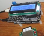
The demonstration code accepts input from the Up/Down keys that increments and decrements a byte variable that is displayed in the top row of the LCD, with no LZB. The Left/Right(Spelled Rigth on the PCB!) keys control the brightness of the backlight, with the PCM value being displayed with LZB in the bottom row of the LCD.
The demo software is attached to post #2 while the I/O interface routines are attached to post #3. I think the code is well commented and should be self explanatory. If not, just ask questions") .
.
Hardware
The LCD Keypad Shield (DealExtreme SKU 118059) has a blue backlit LCD with built-in N/S/E/W/Select(& Reset) keys in a small keypad. It is 100% compatible with the PICAXE AXE401 Shield: just a matter of plugging it into the AXE401, develop and download some driver software and play!
The LCD uses the 4-bit parallel interface to a Hitachi HD44780 compatible driver chip. The backlight is wired to accept PWM, allowing software control of the illumination and, consequently, power drain. So the unit uses 4 data, 2 control & 1 pwm output pins from the 28X2.
The keypad uses a resistor ladder, so key presses are decoded using an ADC channel. The values are steady, so only 8-bit ADC is required.
The contrast is controlled by the (blue) multi-turn pot located in the top left of the photos. The backlight LED can be seen at the right of the display screen. The trusty PICAXE AXE401 shield can be seen, almost hiding, under the LCD/Keypad board.
Software
Attached (in the next two posts) is the test software that I wrote to test the LCD and keypad. I have included routines to write data to the LCD from EEPROM and RAM. Routines to allow byte and word values to be written to the screen, with and without leading-zero-blanking. The code uses just 2 registers (plus b0, with contents preserved) and 23 bytes of RAM. Some of that RAM is only used for the demo, as is a few bytes of EEPROM.
The keypad code places the key value in RAM after the release of a button, so that a single keypress does not get accidently reused. If you want, you could use a background timer to double the number of key outputs to 10 by including press-and-hold key values.
Demo Code
The demonstration code accepts input from the Up/Down keys that increments and decrements a byte variable that is displayed in the top row of the LCD, with no LZB. The Left/Right(Spelled Rigth on the PCB!) keys control the brightness of the backlight, with the PCM value being displayed with LZB in the bottom row of the LCD.
The demo software is attached to post #2 while the I/O interface routines are attached to post #3. I think the code is well commented and should be self explanatory. If not, just ask questions
.
Last edited: