Although I've been doing automation and controls for years, it's been at the system software level -- i.e., "take this and put it there and tell me when you've done it". I've always been jealous of the guys on the floor doing the cool stuff, and decided to give it a try after running into the PICAXE line of products.
My intention is to build a simple and generic relay controller module that I eventually can hang sensors off and stick on a network. Eventually, I'd like to replace the '485 with RF ( The Sparkfun 2400 is so economical - see specs here ), but because I'm a nooby I figured it best to begin with wires I can probe and troubleshoot.
I'll initially drive the components from a PC, but plan to build a PICAXE-based control module with LEDs, buttons and knobs fully festooned with blinking LEDs. Maybe hang one of those very cool vDrive USB drives off it. Add a Bluetooth interface. Maybe a brainwave frequency analyzer. You know, all the things a gadget guy *really needs* to flip a switch.
I took some electronics classes early in my college career, but that was way back in the days of the PLC, the TRS-80 and the Timex Sinclair and I've forgotten most of it.
I started with what I believe to be a pretty good tutorial project and attempted to build out from there.

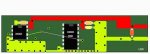
Download ExpressSCH schematic here...
Data sheet for the relay (L1) is here...
Data sheet for the diode (D1) is here...
Data sheet for the amp (Q1) is here...
Data sheet for the MAX485 (U1) is here...
My understanding (which probably is wrong) is that with this design, I can setup interrupts on the 8M's port2 (IO2, leg 5 -- I believe these all refer to the same pin) to wake up when data is available, which I'll read from port0. I'll also write to port2 after I set port2 (which I can only do if it's low).
I kind of like this strategy (which I got from here), because I think the code will be cleaner.
A couple questions for any and all that would care to share their experience...
1. Will this circuit work? I'd kinda hate to see smoke coming from my first project.
2. Are there significant drawbacks to the design? I'm sure there are better ways to skin this cat, but I doubt that I'd understand them at this point on my learning curve.
3. Can the schematic be improved in terms of placement of elements? It seems to me that the schematic ought to clearly convey the "logic" of the design which is different than the layout of the board.
Then again... I could be wrong - and probably am.
Thanks in advance for your help. I've kinda been obsessing on this. I have all sorts of gadgets I've always wanted to build.
My intention is to build a simple and generic relay controller module that I eventually can hang sensors off and stick on a network. Eventually, I'd like to replace the '485 with RF ( The Sparkfun 2400 is so economical - see specs here ), but because I'm a nooby I figured it best to begin with wires I can probe and troubleshoot.
I'll initially drive the components from a PC, but plan to build a PICAXE-based control module with LEDs, buttons and knobs fully festooned with blinking LEDs. Maybe hang one of those very cool vDrive USB drives off it. Add a Bluetooth interface. Maybe a brainwave frequency analyzer. You know, all the things a gadget guy *really needs* to flip a switch.
I took some electronics classes early in my college career, but that was way back in the days of the PLC, the TRS-80 and the Timex Sinclair and I've forgotten most of it.
I started with what I believe to be a pretty good tutorial project and attempted to build out from there.
Download ExpressSCH schematic here...
Data sheet for the relay (L1) is here...
Data sheet for the diode (D1) is here...
Data sheet for the amp (Q1) is here...
Data sheet for the MAX485 (U1) is here...
My understanding (which probably is wrong) is that with this design, I can setup interrupts on the 8M's port2 (IO2, leg 5 -- I believe these all refer to the same pin) to wake up when data is available, which I'll read from port0. I'll also write to port2 after I set port2 (which I can only do if it's low).
I kind of like this strategy (which I got from here), because I think the code will be cleaner.
A couple questions for any and all that would care to share their experience...
1. Will this circuit work? I'd kinda hate to see smoke coming from my first project.
2. Are there significant drawbacks to the design? I'm sure there are better ways to skin this cat, but I doubt that I'd understand them at this point on my learning curve.
3. Can the schematic be improved in terms of placement of elements? It seems to me that the schematic ought to clearly convey the "logic" of the design which is different than the layout of the board.
Then again... I could be wrong - and probably am.
Thanks in advance for your help. I've kinda been obsessing on this. I have all sorts of gadgets I've always wanted to build.
Last edited:
")