Ok my goal is to make a 360 controller modded with a picaxe-18 chip so that it can be flashed/programmed while still in the controller (via the usb programming cable), and I also want it to have control over all 8 of the buttons on the controller including left bumper, right bumper, left trigger, right trigger, X, Y, B, and A. I'm planning to install 2 additional action buttons that can be used to do common macros or rapid fire on any of the 8 main xbox controller buttons. If possible I would like to wire the triggers to inputs on picaxe as well so they can also be used to shoot/rapid fire etc. I would like to note that I do not have any experience with this really at all other then a little soldering, and some basic programming experience in visual basic. Only one way to learn though right? lol. I have read every tutorial and thread I could find on modded xbox 360 controllers and I'm almost done reading the manual on the picaxe chips but I still feel like I could use some help.
The controller I am planning to use is the newer USB wired CL board controller and the board looks like this:
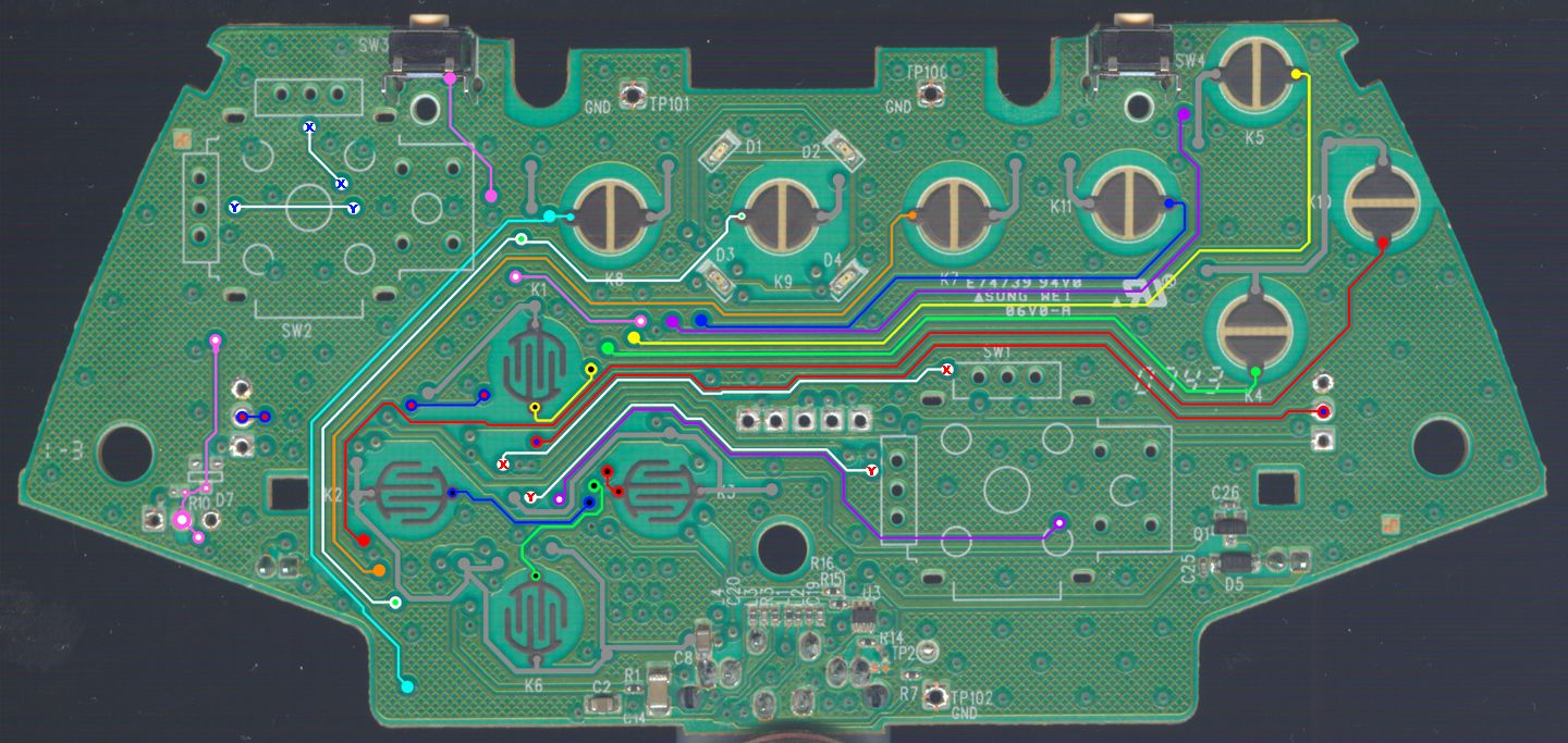

and it can also be viewed on this forum with more info:
http://forums.xbox-scene.com/index.php?showtopic=635462
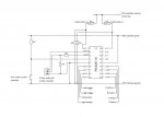
I will be installing 2 extra buttons, the reset switch for the picaxe chip, and the 3.5mm headphone jack for flashing the chip into the controller. I do not even have any experience reading or drawing electrical diagrams but I have made an attempt to draw up some plans for this mod and I was hoping someone could take a quick look at them and maybe tell me if it would even work or possibly help me with any errors I've made. My diagram does not include an LED or trigger wireing yet.
Here is the diagram I drew up:

I guess my questions are:
1. Will this diagram even work?
2. What can I fix on it?
3. Where is a good place to draw power and ground on this controller?
4. Are the 360 controllers power supply 3v like the wireless ones?
5. Will 3v be enough power to run the picaxe chip?
6. Is it possible to use the triggers to control the picaxe as well?
Thanks in advance for any help.
The controller I am planning to use is the newer USB wired CL board controller and the board looks like this:
and it can also be viewed on this forum with more info:
http://forums.xbox-scene.com/index.php?showtopic=635462
I will be installing 2 extra buttons, the reset switch for the picaxe chip, and the 3.5mm headphone jack for flashing the chip into the controller. I do not even have any experience reading or drawing electrical diagrams but I have made an attempt to draw up some plans for this mod and I was hoping someone could take a quick look at them and maybe tell me if it would even work or possibly help me with any errors I've made. My diagram does not include an LED or trigger wireing yet.
Here is the diagram I drew up:
I guess my questions are:
1. Will this diagram even work?
2. What can I fix on it?
3. Where is a good place to draw power and ground on this controller?
4. Are the 360 controllers power supply 3v like the wireless ones?
5. Will 3v be enough power to run the picaxe chip?
6. Is it possible to use the triggers to control the picaxe as well?
Thanks in advance for any help.
Attachments
-
 39.3 KB Views: 17
Last edited: