360 controller picaxe-18 mod help

Bonafid3

New Member
Ok my goal is to make a 360 controller modded with a picaxe-18 chip so that it can be flashed/programmed while still in the controller (via the usb programming cable), and I also want it to have control over all 8 of the buttons on the controller including left bumper, right bumper, left trigger, right trigger, X, Y, B, and A. I'm planning to install 2 additional action buttons that can be used to do common macros or rapid fire on any of the 8 main xbox controller buttons. If possible I would like to wire the triggers to inputs on picaxe as well so they can also be used to shoot/rapid fire etc. I would like to note that I do not have any experience with this really at all other then a little soldering, and some basic programming experience in visual basic. Only one way to learn though right? lol. I have read every tutorial and thread I could find on modded xbox 360 controllers and I'm almost done reading the manual on the picaxe chips but I still feel like I could use some help.

The controller I am planning to use is the newer USB wired CL board controller and the board looks like this:
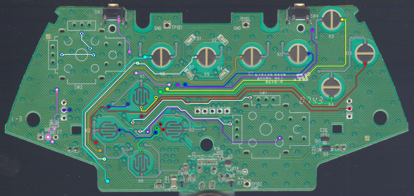

and it can also be viewed on this forum with more info:
http://forums.xbox-scene.com/index.php?showtopic=635462
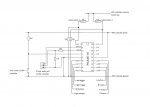
I will be installing 2 extra buttons, the reset switch for the picaxe chip, and the 3.5mm headphone jack for flashing the chip into the controller. I do not even have any experience reading or drawing electrical diagrams but I have made an attempt to draw up some plans for this mod and I was hoping someone could take a quick look at them and maybe tell me if it would even work or possibly help me with any errors I've made. My diagram does not include an LED or trigger wireing yet.

Here is the diagram I drew up:


I guess my questions are:
1. Will this diagram even work?
2. What can I fix on it?
3. Where is a good place to draw power and ground on this controller?
4. Are the 360 controllers power supply 3v like the wireless ones?
5. Will 3v be enough power to run the picaxe chip?
6. Is it possible to use the triggers to control the picaxe as well?

Thanks in advance for any help. :D
 

Attachments

Last edited:

inglewoodpete

Senior Member
First, welcome to the PICAXE forum.

I am not a game controller user or modifier. My teenaged son doesn't often let me near his :)

To answer your questions as best I can:
1. The circuit you have provided should work*. I have to say that the limiting factors will be the available supply voltage and the interfacing requirements (Eg will the high- and low-output voltages be interpretted correctly by the existing controller circuitry?) * Added 28-May: The PICAXE output pins may need protection from presses of the controller's existing buttons. Eg if PICAXE o/p is high and a button is pressed and connects the output to the 0v line, effectively short circuiting the PICAXE output.
2. Fix? The PICAXE-18 is a really old chip. Did you nick it from school? Of course, it will probably do if it will run on the available supply voltage. Voltage-wise the following PICAXEs may be more suited: 08M, 14M, 20M, 28X1. However the M-series have a limited program memory (depends on how efficiently you can write your code). The 28X1 has a lot more legs to accomodate!
3. No idea. Check info on gaming controller modification websites. Try a search for "XBOX" on this forum.
4. See 3.
5. The PICAXE-18 is supposed to run on 3.0v but does the XBOX controller's supply have enough spare capacity to supply the PICAXE chip as well? See 3 for more answers.
6. The triggers should be able to control the PICAXE as well, although there may be interference either way between the XBOX controller chip and the PICAXE.

There has been a lot of discussion on this forum and many others on modifying game controllers. There have been many before you and many to follow.

A word of caution: take care when interfacing to an existing controller circuit. It is easy to damage the printed circuit tracks in the controller.

One final point. You may be able to get the PICAXE-18 to run but may have trouble programming it on a 3v supply. You may need to move the chip to a programming board powered by 3 x AA Cells to get your code downloaded.
 
Last edited:

Bonafid3

New Member
Thanks

Thanks for the help and reply, I do know that the high/low signals will be interpretted as button presses as I have seen a video on youtube of a modded controller with a picaxe 14M chip in a simular way to what Im trying to do. However the M14 does not have enough input,output pins to do what I need. I am also considering the 20M chip but I can't find a retailer who sells them in canada so I decided the 18X was as close as I could find. Also the 14M mod I seen on youtube was in a wireless controller which is powered by 2 AA batteries = 3v but the optional power pack 2.4v did not work for the chip. I will be using a USB controller which Im hoping has equal or more power to work with. I wish the user on youtube had more details about how he wired it up or a good tutorial on this but all I can find is 08M rapid fire chip mods which are just simple rapid fire modes and not able to macro all the buttons on the controller. I more less wanted to make sure the logic in my circuit was ok so that once I wire it up I just have to start playing with code and flashing the chip to do different things. Thanks again for the help.
 

inglewoodpete

Senior Member
You mention the 18X chip this time. Note that its working voltage range is 4.0 to 5.5volts. You may not get enough volts to run the 18X.

As mentioned previously, the 14M and 28X1 will run on as low as 2.0v
 

Bonafid3

New Member
yeah sorry I didn't know there was much of a difference between the 18 and 18X chip. In the picaxe manual it says all chips run between 3v - 5.5v except for the special X2 chips which are 1.8v - 3v. I'm not sure if there is enough room inside the controller for a 28 pin chip but one that runs on 1.8 - 3v would be ideal.
 

Bonafid3

New Member
I just got some new info from another forum and found out the USB wired xbox 360 controllers are 5v. The controller itself requires 5v, 400mA but someone also mentioned that the xbox360's USB ports put out 5v and more mA then a normal USB port. Anyway Im going to test this tomorow and see if it is truely 5v and if so I'll most likely be looking at the picaxe 18X or 20M chip for my mod project. I believe the 18X has way more room for code.
 
Last edited:

hippy

Technical Support
Staff member
It is a shame that the controller moding community rarely describe what they are doing in detail nor explain why and how what they are doing works. I haven't yet seen a properly reverse-engineered schematic for an xbox 360 controller and interfacing to it is often more than just connect this to that, there also a variety of different controllers with different circuits.

USB does indeed carry a 5V supply but it does not necessarily follow that the internal electronics runs at 5V. Connecting a 5V powered device to 3V3 electronics requires care and done wrongly can destroy things.

It is also not necessarily a case of choose a PICAXE, connect its output pins to a switch contact and, bingo!, automated button control. In particular, when automating triggers it is necessary to design the circuit so the triggers can be used manually as well as automated and that using the triggers while in automated mode doesn't destroy the controller or PICAXE.

When copying a specific design ( use this, connect that, run this code ) that probably works, but when changing the design, going to a different PICAXE, one needs to understand what one is doing, how things need to be controlled and how that is achieved. Without that there's a good chance of a design which won't ever work and at worse can destroy the controller.

Modding a controller is primarily a matter of electronic interfacing in a safe manner and this seems to be the one area which information is sorely lacking.
 
Top