binary1248
Senior Member
I need a suggestion on how to sync my pendulum clock to a precision (RTC) 1 sec pulse.
The clocks are home built wooden gear clocks and the pendulum is given a kick from a coil burid in the base.
The pendulum has a magnet in it and as it passes the base, a tiny reed switch senses the bottom position. Then the 08m2 gives the pendulum a tiny repulsive kick after passing BDC (bottom Dead Center).
Now the pendulum still has to be carefully adjusted for swing period and I can get 10 sec over 10 hrs accuracy.
Since I already build in a 08m2 to time the pendulum kick pulse, if I could add a RTC chip with the 08m2 I should be able to get many months of accuracy.
I have built two of these clocks and of course people are amazed and watch them since all the gears are open and exposed.
You can see one of mine in action at:
https://www.youtube.com/watch?v=WtaijXGS4Gs
.
Yes, it's an overkill, but it's fun to apply advanced technology to old technology.
.
This happens twice a second, once for right swing, 2nd for left swing. But I was thinking to use only one direction swing and create a 1 sec timing pulse for the RTC.
I have an extra input to the 08m2 for the 1 sec timing pulse from the RTC.
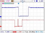
I don't need code, just suggestions on how to generally do this. Attached is an waveform capture of the control sense and drive pulse.
The lower is the reed switch, the center pulse is dead center over the reed switch, I only use the leading edge of the reed switch pulse for delay timing
.
Click on image to expand.
.
Here is current code, pretty simple.
Paul
The clocks are home built wooden gear clocks and the pendulum is given a kick from a coil burid in the base.
The pendulum has a magnet in it and as it passes the base, a tiny reed switch senses the bottom position. Then the 08m2 gives the pendulum a tiny repulsive kick after passing BDC (bottom Dead Center).
Now the pendulum still has to be carefully adjusted for swing period and I can get 10 sec over 10 hrs accuracy.
Since I already build in a 08m2 to time the pendulum kick pulse, if I could add a RTC chip with the 08m2 I should be able to get many months of accuracy.
I have built two of these clocks and of course people are amazed and watch them since all the gears are open and exposed.
You can see one of mine in action at:
https://www.youtube.com/watch?v=WtaijXGS4Gs
.
Yes, it's an overkill, but it's fun to apply advanced technology to old technology.
.
This happens twice a second, once for right swing, 2nd for left swing. But I was thinking to use only one direction swing and create a 1 sec timing pulse for the RTC.
I have an extra input to the 08m2 for the 1 sec timing pulse from the RTC.
I don't need code, just suggestions on how to generally do this. Attached is an waveform capture of the control sense and drive pulse.
The lower is the reed switch, the center pulse is dead center over the reed switch, I only use the leading edge of the reed switch pulse for delay timing
.
Click on image to expand.
.
Here is current code, pretty simple.
Code:
;April 30 2015   PEH
;   *************************
;   *Pendulam Timer         *
;   * Flie = PendulamtmrXX  *
;   *************************
;
;
; Changed timing on dly & push 5/8/2015
; Added test points (red, grn, yellow) 8/31/2016
; Added startup seq to get pendulam going 9/14/2016 (not working)
;
;
#picaxe	08M2
#com 4	'specify com port
;
#no_data   'save some load time
'#no_table
'#terminal 4800

;
symbol coilpwr=C.2 ;pin 5 on chip


symbol inputx=pin3   	;input pin 4 on chip
				'symbol outblck=pin4  ;input pin 3 on chip  not used
symbol dly = 20		;was 20
symbol pushx = 55		;was 50, then 55
W7=0

Start:
	input 3,4         ;make ports 3 & 4 inputs, physical pins 4,3
  ;Auto startup
	;for b1 = 1 to 20
	;high coilpwr ;coil pwr on
	;pause 50   ;red led on, coil pwr
	;low coilpwr  ;coil pwr off
	;pause 400
	;next b1


	low coilpwr   ;Coil pwr off
	'

	'serout c.0,T2400_4,(0XFE,0X51) 'Clr LCD Display;
	'pause 100
	'serout c.0,T2400_4,("READY ...........") 'Display value follwed by Hom
	'Pause 100
	'serout c.0,T2400_4,("Clearing LCD ",0XFE,0X51,"READY") 'clear lcd command

	;
	Main:
	'
'	serout c.0,T2400_4,("Clearing LCD ",0XFE,0X51) 'clear lcd command

 Do
	;	Find entry switch tripped
	if inputx=0 then  ;physical pin 4, no bounce detection needed
		'  GREEN TEST LEAD
	  pause	dly    'let pend swing past center
	  high coilpwr 'Apply coil power
	  high c.1    'strobe led test 'YELLOW TEST LEAD
	  low c.1

	  pause pushx     'keep pwr on for delay time ...RED TEST LEAD
	  low coilpwr  'remove coil pwr
	 pause 400 'stay off in case pendulam stops and reed sw stays closed
	 		'prevent coil overheat
 	 W7=W7+1   'for some timing testing only send to LCD
  'serout c.0,T2400_4,("Clearing LCD ",0XFE,0X51) 'clear lcd
  'serout c.0,T2400_4,("CTS = ",#W7,0XFE,0X46) 'Display value follwed by Home Cursor

	 endif


	  low coilpwr	'

  Loop
Paul
Last edited:
")