wiring basic ...

louisyuikin

New Member
Hi

I'm new to Picaxe and electronics in general. I have just finished soldering the AXE090 board and it downloads code OK.

Now, how do I ''wire'' the components on the board. On one side there are pins for the mcu and on the other sides markings for components (LDR' SW1, 2,3,...)

Suppose I want to experiment with tutorial no.6 (using analog sensors)...how the I proceed to make the connections...

Could anybody suggest a post in the forum or pages in the manual to get me started. Or maybe a link on the web.

Thanks

LouisY.
 

piglet74

New Member
I use these from radio shack.

http://www.radioshack.com/product/index.jsp?productId=2103801&cp=2032058.2032230.2032265&parentPage=family

If the link doesn't work it's called a Solderless Breadboard Jumper Wire Kit. most of the playing around that I've done so far I just use a jumper wire from the input or out pin to the device (switch, ldr, led etc...). If I'm worried about polarity, I test it with a meter by putting a jumper in the V+ or V- and then seeing what I get between the device and rail. Page 5 of the axe090 manual describes how they work now that I look at it.

So for example the pot has its legs between the V+ and gnd. The wiper is attached to the hole for the pot so it makes a voltage divider. If you attach that to an input pin and run a readadc on that pin it will give you a value based on the voltage divider which equates to a position on the pot. Hope this helps.

Rob
 

moxhamj

New Member
I agree with Piglet. I bought my solderless breadboard when I was 12 and after 26 years it has made thousands of projects and is still working fine. I do all my picaxe programming on the board as well and only make a soldered version once I am certain it works.
 

louisyuikin

New Member
Thanks Rob

I already have the Breadboard Jumper Wire but my question is more how to wire the whole circuit. I will try to read readadc as you suggest.

LouisY.
 

manuka

Senior Member
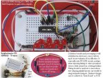
26 years! My own enthusiasm for breadboards is only too well known... Although neat layout wiring should be the norm,the flexible jumpers (below) brilliantly suit initial hookups. We get ours via NZ schools outlet Surplustronics => http://www.surplustronics.co.nz/shop/product-HW0015.html ,with 75 leads for NZ$4.50 (~US$3) working out at about £1.50 a pak or ~2p each. HIGHLY RECOMMENDED- Dr_A would love them! Stan
 

Attachments

Last edited:

louisyuikin

New Member
Hi to all

Thanks for your answers, but my question is still ''...how the I proceed to make the connections...''. In other words: I've got all the jumper wires and the board, but I want to know in which ''holes'' do I plug the wires.

It is my first experience with a breadboard and of course with a mcu board !!!

Thanks

LouisY.
 

moxhamj

New Member
Put in a chip in the middle with a row of pins along the top and bottom. There will be a notch on the chip - that notch always goes to the left and then leg 1 is the bottom left corner. Connections go up and down, so the top left pin is now connected to all the holes above that pin. Generally there are 5 holes so the chip uses one and you have 4 more to connect things to. Then there are the power supply rails at the top and bottom - they go from left to right. Sometimes with the bigger boards they are split in the middle as well.

I didn't understand the very first breadboard I got either, so I remember I peeled a bit of the backing off and looked at the metal connections inside. Then it made sense. But I wouldn't suggest doing that! I'll try to find a picture (someone else might have one). There are also printed circuit boards with the same layout so you can transfer designs over from breadboard to soldered board.

Addit: http://en.wikipedia.org/wiki/Breadboard third picture down on the right. The horizontal line down the middle isn't there on solderless breadboards.
 
Last edited:

inglewoodpete

Senior Member
Louis, The PICAXE website does not appear to list the AXE090 manual. It is actually there at http://www.rev-ed.co.uk/docs/axe090.pdf If you don't have it, I strongly suggest you print it (5 pages). The last 2 pages explain fairly clearly how to use the breadboard.

Start simple: flash a LED with code then go to other slightly more advanced circuits. Have a look at http://www.rev-ed.co.uk/docs/axe092.pdf (schools experimenter). It has several components actually hard-wired already but you can connect your components on the 090 in a similar fashion.

Other simple circiuts you may want to try would be to use the LDR as an input. Use it with the ReadADC to switch the LED on and off at a threshold light level. Using the same wiring, change the code to flash the LED at different rates according to the ambient light level.
 

eclectic

Moderator
Check please.

Louis.
I've just had a very quick scan of your link.

Please could you proof-read it further.

If it's for an 08M, then here are some potential errors;

byte integer = 0 - 155

And possibly others?

e.
 
Last edited:

louisyuikin

New Member
Eclectic

That link provided me with a description of the AXE 090 (sections Introduction and Hardware)

For the rest of the arcticle, I will let you proof-read the code since I'm really a beginner!

LouisY.
 

moxhamj

New Member
Isn't that great! I talk about pulling the back off my protoboard, and Manuka goes and shows a photo of what it looks like.

When I first got into electronics I bought a number of those PCBs from Dick Smith (and others) that had the same layout as the protoboard. Then just replicate the circuit. (Later I got into point to point wiring using wire wrap wire but you need a wire wrap stripper tool for that. 4th picture down at http://drvernacula.topcities.com/RFDataLink.htm More recently I've been getting boards made in China http://www.instructables.com/id/Professional-PCBs-almost-cheaper-than-making-them-/ but I wouldn't recommend that for one-offs.) I'd study Manuka's website as it is targeted to getting things working quickly and is targeted to beginners.
 
Top