- Wireless serial with XRF modules... and 20x2 ... also 20m2 - Is it me or the chips?

Blazemaguire

Senior Member
Hi

I've been reading scary things about the error on the serial transmission rates for the 20x2 and 20m2 chips... annoyingly I have brought 2 of both for my first forage into the 'new picaxe' and am not sure if they are the cause of the problems I'm having, or if it's me being stupid as i'm totally new to serial communication. ( - I've only got 20x2 and 20m2 chips as I've been away from PICAXE for a while, the last chips I used were the 18x series!)

I've also brought two of the XRF wireless modules and am trying to send simple information back and forth between them - At present i'm just incrementing a variable on one chip every second, and transmitting it to another chip where I want the variable displayed on the LCD screen. - Code is below... 'Should' be really simple to do right?

TRANSMITTER

init:
pause 1000


b1=1
main:

inc B1
serout b.5,T9600_8,(b1) 'transmit through XRF
pause 1000
goto main

RECEIVER

init:
pause 1000


main:


serin b.6,T9600_8,b1 ; Read in wireless serial into b1
serout b.7,N2400,(254,1) ;clear LCD
serout b.7,N2400,(254,128) ;Goto line 1, pos 1 of LCD
serout b.7,N2400,(#b1) ; write variable B1
goto main


I'm definitely getting data transmission, as the LCD changes numbers every second in line with my transmission coding... sometimes I even get the numbers arriving in incremental order for maybe 8 times in a row, and then i'll get a random number. - If I cut power to the transmission PIC circuit then nothing arrives... hence I'm positive I've wired the modules correctly. The XRF's are apparantly supposed to handle all error checking and are supposedly 'plug and play'.... though, like I said, I'm a novice with this area of PICAXE!

Now.. because i'm such a complete novice at serial comms (and actually, BASIC as well... i'm used to the flowcharts, but quickly learning the benefits of BASIC) I don't know if its something i'm doing wrong, or if it's to do with the serial transmission error on the X2 and M2 chips that I've read about on this forum.

Annoyingly the XRF wireless modules are default configured to run at 9600 baud - They can be changed apparently, but I've no idea how to do this as the documentation is very unhelpful. - If I could change the baud of the XRF module then i'd try it at the more stable serial speeds and see if that helped.

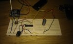
Could someone wiser and better looking than me look at my coding above and tell me if there are any novice problems likely to be causing it. - Failing that, Are there any problems with my circuits? - Bad photo of the reciever circuit attached... the transmitter XRF module is wired the same way.

Thanks

Rob
 

Attachments

MPep

Senior Member
Would adding a SETFREQ help? You are telling the transmitter to "serout b.5,T9600_8,(b1) 'transmit through XRF", but does the PICAXE default to that? Just a thought :)
 

Blazemaguire

Senior Member
Shouldn't need to do that for the X2 chips (as they default to 8mhz) - Tried it with the 20m2 and just got rubbish sent through.. is more stable without. - Any other thoughts
 

g6ejd

Senior Member
I would increase the PAUSE 1000 in the TX routine to say 5000 and then see if you still get the same errors/issues. it takes a while to clear the LCD, etc, it may all be a little slow sending that data to the screen, if that does not solve it, then I would go for not clearing the screen with 254,1 to eliminate as many factors as possible.

Also I suggest adding a small capacitor say 0.01uF or 0.1uF or anything small right across the PICAXE power pins as there is RF flowing around on TX.
 

jedynakiewicz

Senior Member
It has been acknowledged that the setting 9600_8 on the 20X2 chip appears to be out of specification.
The workaround on a 20X2 is to simply use a different setfreq frequency for 9600 baud, e.g. 9600_32.
A new firmware version is promised, but the workaround seems to work okay. Just run the 20X2 at 32 and you should be fine. And as G6ejd suggested, a decoupling capacitor across the powerleads is essential.
 

Blazemaguire

Senior Member
It has been acknowledged that the setting 9600_8 on the 20X2 chip appears to be out of specification.
The workaround on a 20X2 is to simply use a different setfreq frequency for 9600 baud, e.g. 9600_32.
A new firmware version is promised, but the workaround seems to work okay. Just run the 20X2 at 32 and you should be fine. And as G6ejd suggested, a decoupling capacitor across the powerleads is essential.
Thanks, I've tried that (with both the 20x2 and the 20m2) - It actually makes it far worse... rather than getting a batch of numbers received correctly and then it messing up, it's just messed up from the start!

I've taken the clear screen command out of the loop, and put the decoupling caps in as suggested - Increasing the pause in the loop just makes me wait 4 seconds longer for the same issue! - No difference.


Kind of frustrating - Anyone know how to program the XRF modules so the baud rate can be changed to something better suited to the PICAXEs I have? - I gather it's a serial interface method to reconfigure, but I can't figure out how or what I should be doing - I've downloaded the software interface for doing it which looks really simple, but cannot establish a connection with the modules (but then, I am guessing - There is no explanation on how to do it that I can find) - Not sure if I need special hardware, or if it can be done with the PICAXE USB to serial convertor I have already.

What baud is an 18X capable of? I have a few of them at work. - Annoyingly the ones I have at home just don't seem to want to work either or i'd have swapped them out during my testing.
 

Blazemaguire

Senior Member
@ Eclectic - Post number 80 seems to apply to the similar (but different) modules... ERF and URF .. I have the XRF which seems slightly different. - It has it's own programme for adjusting it's settings which I have, but I can't get a connection.


The instructions are here... but not sure what an ax210 adaptor is... is that a standard USB to serial or something else?

Using CCFlashProg to serially program XRF
1. Attach the XRF to a PC using either the Cisceo FTDI USB interface or something similar (eg sparkfun xbee explorer, AXE210), CCFlashProg assumes the XRF baud rate is 9600bps.
2. Start CCFlashProg.exe
3. Select the serial port that XRF is connected to
4. Select the hex file to program to the XRF
5. Press program – if it fails to start try again, the serial timing could be a little different between the PC and XRF
6. After it programmed, press verify – if it fails to start, try again
7. If all is reported OK press commit.
8. XRF will restart with the new firmware
9. (Optional) Using a terminal emulator app (XCTU, Hyperterm etc) issue +++ to the XRF and then using the ATVR command check the new software revision number.
 

Haku

Senior Member
Do both setups have the input of the XRF wired to the Picaxe?

If so you must pull the line high or you will likely get problems with communicating between the two modules.

For the breadboarded 20m2 pictured above put this line into the start of the code: high B.5

I only discovered this because I bought 4 modules from the start, allowing me to have 2 or 3 running on Picaxes which are communicating to each other, with one left over plugged into a TTL-USB adaptor allowing me to eavesdrop on the wireless communications. I noticed random '0's being transmitted when the XRF input line was connected to a Picaxe which had its pin set to input (floating), pulling the pin high solved this problem.

As for the pause at the beginning of the code, the XRF boots up incredibly fast (just a few ms) so a pause of 20ms should suffice, if you really want to be sure then make it 5000ms in case it has gone into AT command mode as that times out after 5 seconds.
 
Last edited:

Goeytex

Senior Member
The baud rate of the 20x2 is not the problem as long as you have the processor clock set with "setfreq M16" and you use serout T9600_16. Serial com to the display will then be serout N2400_16. There should no reason program the XRF for a different baud rate.

If it were me, I would be using the 20X2 and hardware hserout with background receive for com between the XRF and the Picaxe. I have NEVER had problems with Picaxe hardware serial.
 

hippy

Ex-Staff (retired)
I'm definitely getting data transmission, as the LCD changes numbers every second in line with my transmission coding... sometimes I even get the numbers arriving in incremental order for maybe 8 times in a row, and then i'll get a random number.
The code you have looks right and baud rate should not be an issue.

Baud rate errors are primarily a problem when a receiving device doesn't have the usually expected tolerance to baud rate errors of the serial stream it sees. It's highly unlikely that baud rate would change significantly enough to mostly work but sometimes fail so one would have to be on the borderline of tolerance for that to happen. An ERF module's tested tolerance to baud rate error is what one would expect of normal serial receive, around +/-5% and any 20X2 or other PICAXE baud rate error is well within that. Though I don't have test results for an XRF there doesn't seem any reason to believe that would be different.

The setup you have should work at 9600 baud at 20X2 default frequency with 'out of the box' XRF modules. There should be no need to change operating frequency, nor to reprogram the modules. I would suspect some hardware, electrical or environment issue rather than software, firmware or baud rate issue.

What happens if you simplify the receiving code as eclectic suggests in post #4 ? It could be that the data is being received correctly but the display of it is wrong.

Also, have you pulled-up the RX input of the receiving module as Haku suggests in post #9 ? If not that can cause unexpected receiver behaviour.

Perhaps record a reasonable sized sequential list of values you receive and post those along with circuit diagrams of sender and receiver including details of power supplies.
 
Last edited:

Technical

Technical Support
Staff member
Also, have you pulled-up the TX input of the receiving module as Haku suggests in post #9 ? If not that can cause unexpected receiver behaviour.
We would suspect this also. And remember connected to a leg of a PICAXE that is not actively currently configured as an high output (ie left as an input) is the same as floating.
 

Blazemaguire

Senior Member
Thanks guys,


It now is much better.. at least going from 1 to 65 in individual increments, and then it just goes mental ... 216, 843, 941, 265,227, 100 etc... I get about 20reps of bad data, and then it recovers for maybe 10 in a row.. and then gets bad again.. the ratio of bad to good getting worse and worse as time progresses.

Everytime it goes bad at 65! - This is approx 6 times better than before!


The setfreq m16 just gives me crazy characters (heiroglyphics!) across the screen where I diddnt even tell them to go.

Getting there... - Ironically - 9600_8 seems most stable - _16 and _32 just give errors straight off the bat.


Circuit is as pictured in Post 1, with decoupling caps on PIC power pins now - Am running off 2 (fresh) AA batteries on each- No 3.3V regulator - though I do have one... worth a try?
 

Blazemaguire

Senior Member
Actually, now fixed! (so I can get on with what I was wanting to do!) - I misread the post about setting setfreq to m16 and forgot to update the serout for the OLED instructions to N2400_16 as well... this was why the OLED was showing garbage. - Have just had zero to 255 10 times in a row with no errors. YES!

Merci beau Monsieurs
 

Technical

Technical Support
Staff member
So to summarise for others,

- 9600 baud works at any setfreq on both 20X2 and 20M2 with the XRF / ERF / URF modules
- When used as a receiver only, the unused pin on the XRF/ERF radio module (marked RX) must never be left floating. On XRF it must be pulled high, on PICAXE ERF it must be pulled low.

When RX is unused in a program but still connected to a PICAXE pin, make sure you use the appropriate high/low on that pin at the start of the program to make sure the PICAXE pin is configured as an output (so that it correctly drives the RX pin).
 
Last edited:
Top