Which amplifier to use?

Shafto

Senior Member
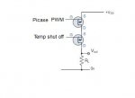
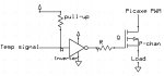
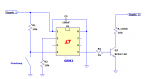
I'm using the PWM output on the picaxe08M2 at 4.5khz flowing about 18mA. The PWM pin on the Picaxe goes to the source of a PNP FET and the drain to the load. The gate of the FET goes to a inverter that is connected to a temperature switch with an open drain output that is pulled up. When the temp gets too high and the temp switch triggers, it goes low, then inverter sends the high signal to the gate of the PNP and turns off the PWM output.

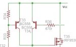
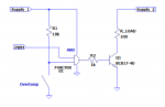
Everything works fine, except now I would like to draw more than 20mA from the PWM pin, so I want to find a way for the Picaxe to send the PWM signal to the gate of a FET and still retain the temperature shutdown capability. I need to amplify the current from the pull up resistor on the temp switch to supply ~30mA, which will go to the source of the PNP, the drain to the load, and the gate controlled by the Picaxe, which will invert the PWM signal, but I can fix that in the code pretty easily.

My question is about how easiest to go about this? I've never implemented a BJT or MOSFET as an amplifier before, but I've been reading about common collector and common drain amplifiers, of which either should likely work? Possibly the common collector being better at lower voltage. If I use a common collector amplifier, when the temp switch goes low, can the base of the BJT be connected directly to ground or should I put a resistor in between?

Or possibly is there some kind of amplifier chip like this schmitt trigger inverter I having been using? http://www.ti.com/lit/ds/symlink/sn74lvc1g14.pdf

The exact same thing with an amplified output instead of an inverted one would be perfect, even though it's only 24mA, I could live with that. Then I wouldn't have any voltage drop like I would with a BJT.

I can make a circuit diagram if anything is unclear. Any suggestions about the best way to proceed?
 

premelec

Senior Member
"I can make a circuit diagram if anything is unclear." - please simplify the question or draw a simple schematic - you know what the thing is but I'm not getting it off hand... It would seem easy to get 24ma out from a PICAXE drive pin if that's all... BJT, MOSFET etc...
 

sghioto

Senior Member
I need to amplify the current from the pull up resistor on the temp switch to supply ~30mA,
Not sure if I understand that statement correctly, but would connecting two P channel FETs in series work as shown in the attachment?

Steve G
 

Attachments

Shafto

Senior Member
I'm never sure if what I'm explaining will be clear or not, since I can see it so clearly myself. I tried. This schematic should do the trick though. This is how it's currently setup.

The output from the temperature switch goes low when it overheats, so normally the input to the signal inverter is high from the pull-up resistor, the low output keeps the p-channel FET conducting the PWM signal until the temp switch activates and everything turns off.

To achieve what I want, the picaxe no longer supplying much current, and just driving the gate of a FET, I could use another FET to get the job done. I'm sure however, that I could also ditch the inverter and just amplify the high signal from the pullup resistor somehow to power the ~30mA through a P-chan FET of which the picaxe sends it's PWM signal to the gate. It's more efficient with components, and I want to learn something new. If there was a chip exactly like the inverter chip, but just didn't invert the signal, that would be perfect, just like putting two in a row. I basically need to take a high impedance source (the pullup resistor) and buffer it to get a low impedance source that can drive ~30mA. Then then 30mA source can go through the source of the p-chan FET, through the drain into the load, and the picaxe can control the gate with the PWM signal. (which will now be off when on and on when off, but I can fix that simply with some code)

I was under the impression that picaxe would only be happy supplying up to 20mA, but even if it's ok a bit higher than that, I would still prefer to provide the current from an outside source and not load up the picaxe since it's powered through a 10ohm resistor and 0.1uF to keep the power to it clean. If I keep the power consumption low I won't get as much of a voltage drop on picaxe V+ every time the PWM signal goes high.

temp schem.jpg
 
Last edited:

inglewoodpete

Senior Member
Wow you sure seem to be trying to do this the hard way!

The attached circuit snip is from a P-channel MOSFET controller that I use for high-powered LEDs. The circuit needs a 4.7k pull-down resistor between the MOSFET's gate and 0v. The MOSFET can be turned off by turning either PNP transistor 'on'. I use PWM to switch the left-most PNP on and off. The second PNP allows a second input to enable and disable the MOSFET.

Depending on your choice of MOSFET, you can switch quite high currents (I switch up to 1.5 amps).
Gated MOSFET.JPG
 

techElder

Well-known member
Shafto, there isn't any reason to even have the "FET" if you are going to run all of the load's current through the PICAXE anyway!

Use the PWM output to CONTROL the "FET"; NOT the load. Use the "FET" to control the load.

That's the main problem with your drawn design.

Look at IWP's schematic. His MOSFET is between the load and a source of power. He controls the MOSFET with two different connections to his processor.
 

hippy

Technical Support
Staff member
I am not quite sure if I am understanding the problem but it seems to me you only want to allow the MOSFET to be driven when the temperature cut-off hasn't activated. The solution to that would seem to be to put an AND gate before the MOSFET or MOSFET driver or to use a MOSFET driver which includes an enable.
 

sghioto

Senior Member
Why not just connect the the Temp signal to an input pin on the Picaxe to control the PWM output ?

Steve G
 

Goeytex

Senior Member
There are many ways to do this. One is with an external circuit. Another is with the Picaxe itself. The first image shows an external method, the second is with a Picaxe using the code below:

Code:
[color=Navy]#Picaxe [/color][color=Black]08M2[/color]
[color=Navy]#no_data[/color]

[color=Green];PowerON Settings[/color]
[color=Blue]if [/color][color=Purple]PinC.3 [/color][color=DarkCyan]= [/color][color=Navy]0 [/color][color=Blue]then   [/color][color=Green];Overtemp !  
      [/color][color=Blue]setint [/color][color=Navy]%00001000[/color][color=Black],[/color][color=Navy]%00001000 [/color][color=Green];int when high[/color]
[color=Blue]else
      setint [/color][color=Navy]%00000000[/color][color=Black],[/color][color=Navy]%00001000 [/color][color=Green];int when high[/color]
[color=Blue]endif [/color]

[color=Black]MAIN:
   [/color][color=Green]'waiting for Interrupt from Temp Switch
   [/color][color=Blue]DO
      Pause [/color][color=Navy]100   
       [/color][color=Green]'Do other stuff here
   [/color][color=Blue]LOOP      

Interrupt:
if [/color][color=Purple]pinc.3 [/color][color=DarkCyan]= [/color][color=Navy]0 [/color][color=Blue]then
   PWMOUT C.2[/color][color=Black], [/color][color=Blue]OFF  [/color][color=Green]'HEATER OFF
   [/color][color=Blue]LOW C.2
   setint [/color][color=Navy]%00001000[/color][color=Black],[/color][color=Navy]%00001000 [/color][color=Green];int when high
   [/color][color=Blue]goto [/color][color=Black]EXIT_INT[/color]
[color=Blue]else
   pwmout C.2[/color][color=Black], [/color][color=Navy]221[/color][color=Black], [/color][color=Navy]443  [/color][color=Green];Heater ON 4500Hz at 50% @ 4MHz
   [/color][color=Blue]setint [/color][color=Navy]%00000000[/color][color=Black],[/color][color=Navy]%00001000 [/color][color=Green]'int when Low[/color]
[color=Blue]endif[/color]

[color=Black]EXIT_INT:[/color]
[color=Blue]return  [/color]
 

Attachments

Shafto

Senior Member
Thanks everyone. AND gate was what I was looking for. I knew something like that must exist, but didn't know enough to find it. More specifically, a NAND gate, since I'm switching high side with a P channel FET.

How is using a NAND gate the hard way inglewoodpete? Maybe you didn't understand what I was looking for. Your circuit would indeed work as well, but I think that using a AND/NAND gate is better since you get some push-pull action on the gate instead of just pulled up or down with a resistor.

Texasclodhopper, the point was to not run the current through the picaxe. I know the schematic does this, I was showing how the circuit is currently set-up and explaining how I wanted to change it from there.

The reason for not wanting to run the output from the temp sensor to the picaxe is to keep the temp control all hardware, and not use up a pin when not needed.

I think an emitter-follower would have worked as well, but there would be a voltage drop, and seemed to be a much more compromising circuit overall. NAND gate was definitely what I was after, not realising I was already using a NOT gate (the inverter).

Thanks again.
 

inglewoodpete

Senior Member
Thanks everyone. AND gate was what I was looking for. I knew something like that must exist, but didn't know enough to find it. More specifically, a NAND gate, since I'm switching high side with a P channel FET.

How is using a NAND gate the hard way inglewoodpete? Maybe you didn't understand what I was looking for. Your circuit would indeed work as well, but I think that using a AND/NAND gate is better since you get some push-pull action on the gate instead of just pulled up or down with a resistor.
My comments related to using the P-channel FET to gate to output of the PICAXE, a solution which does not offer any current gain (amplification) which you were seeking.

When I posted my suggestion, AND or NAND gates had not been mentioned. In reality, the three-transistor circuit in my post is just that: a high powered AND gate. The two PNP transistors form the two inputs of a TTL AND gate. The MOSFET is a high power digital amplifier.

The drive for the FET's gate provided by a 4.7k resistor is about 1mA: a push-pull driver is not necessary. The 4.7k resister is more than adequate for a MOSFET switching PWM of a few kilohertz and less than 100mA. I2R heating of the MOSFET silicon will be insignificant at the low currents that you asking for.

Peter
 
Top