when to use a external resonator

BrendanP

Senior Member
I am aware the X2 parts can use either an internal resonator or an external resonator when timing accuracy is important.

Is there any other benefit to using the external resonator? Does it improve the accuracy of outgoing higher baud rate (ie. 115200) serial coms or I2C coms for example?
 

Dippy

Moderator
An external clock (resonator/crystal) is more precise , more accurate , more stable. Better - full stop.
A typical crystal is better than a typical resonator. Check Data Sheets for spec and app.
It improves timing accuracy in all aspects - including Serial.

Other than that they're awful ;)

IMNSHO: In any circuit where timing is important or fast asynch comms is used then I would ALWAYS use a crystal.
But there are situations where INTOSC is more suitable.
Horses for Courses.
 

MFB

Senior Member
The accuracy of any PICAXE timing function (count, period, pwm and serial coms etc) can be greatly improved by using an external crystal. Although the operation of the I2C and SPI bus is very tolerant of timing errors and would not benefit from a change from the internal RC oscillator.
 

Dippy

Moderator
Yes, good point, that's because they are synchronous serial.

In Asynchronous serial (eg. Serout) each 'half' is totally reliant on timing accuracy (+/- a bit).
You must have seen the dozens of posts about problems with Serout?
 

Minifig666

Senior Member
Can you use an crystal oscillator using just 1 of the resonator pins? If so witch one goes to the resonator and what do you do with the other one? You could get really accurate with a .025ppm posh one. (Around £75 and a 5min warm-up time!)

Sorry, I found it on the PIC data sheet. But, is their any way to get at the 1MHz, 500kHz, 250kHz, and 125kHz clocks on the 28X?
 
Last edited:

Dippy

Moderator
If you have an active (driven) clock source you connect it to OSC1.
Refer to a PIC Data Sheet.

OSC1 is an input and OSC2 is an output. For a 'passive' crystal/resonator the OSC2 drives the resonant device and OSC1 takes the oscillation in - if you see what I mean.

If the pinout is different on some devices you'll have to check.
I think you'll have to cross-reference the particular PICAXE-of-choice with the respective PIC. I'm a pin person so you'll have to get your own legs sorted :)

Bloomin' 'eck - after all that typing ;)
Yeah , just make yourself an oscillator and shove it in.
I'm scared to type anything just in case we go for another edit.
 

BrendanP

Senior Member
This pcb Im working on looks more complex all the time, I'll be surprised if its works first try............ I'll use the external resonator, I need everything going for me I can get.

Dippy, you say a crystal is superior to a resonator. Is there a crystal you would recommend for use with a 40X2 3.3V version?
 
Last edited:

Dippy

Moderator
Well, I reckon nearly any old make (from a reputable supplier) will be OK.
I've used loads and never had a duffer.

For cheap'n'cheerful stuff I tend to use Abracon.
Example 10MHz through-hole:
http://uk.farnell.com/abracon/abl-10-000mhz-b2/crystal-10m-18pf-cl-hc49-4h/dp/1611775
Don't forget you need capacitors.

More accurate/stable crystals means more cost. Sometimes you may need.

And you may find a better range of choice with SMD. Certainly smaller.

A resonator will save a bit of space at the expense of a bit of accuracy and slight loss of stability/drift.
I don't use resonators anymore but when I did I found them better than INTOSC , so don't be under the illusion they're bad.


So, you need to make a judgement call as to which you want to use.
 

BrendanP

Senior Member
Thanks Dippy, I've looked at the link and will find smd equivalent.

You mention caps. Excuse my ignorance but how are they connected and what value?

I see "load capacitance" listed as selection criteria, does a lower figure equate to a better quality part?
 
Last edited:

hippy

Ex-Staff (retired)
Staff member
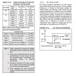
The load capacitors connect from OSC1 and from OSC2 to 0V. A three-pin resonator will have these included so you don't have to worry about them. The PICmicro datasheet will usually suggest values ( 22pF or 33pF AFAIR ) for type and frequency of crystals. Beyond that it's a mystery to me, which is why I'd use resonators or just use whatever they say and keep my fingers crossed :)
 

Dippy

Moderator
Read the Xtal manufacturer's Data Sheet as well as the PIC Data Sheet.
You'll find that many crystal load caps are 15pF and upwards.

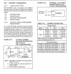
Here are a couple of examples from a 16F Data Sheet.

You don't have to be bang on with your values but don't do too mad.
The examples I showed indicated a Cl of 18pF.


Time to read up... if you want techno stuff ALWAYS try Microchip's site first.
http://ww1.microchip.com/downloads/en/AppNotes/00826a.pdf
and
http://ww1.microchip.com/downloads/en/AppNotes/00849a.pdf


If you want to go the resonator route then that's fine.
If you want better then go xtal.
If you want to go really good then you'll be paying a cosy amount for a compensated osc block of some description, but that's well OTT for 99.9% of projects.
Just get the Data Sheet. If it says CL=18pF then a couple of 18pF to 22pF ceramic capacitors will be fine.

If you read up then I'm not sure what more can be said really.:confused:

I'm puffed out now so good luck. :)
 

Attachments

Last edited:

BeanieBots

Moderator
And don't forget that layout is critical with resonators and crystals.
No long tracks and 0v should ideally be a ground plane.
A few extra inches of track and you'll skew the frequency to a point where it might be worse than the internal oscillator:eek:
 

BrendanP

Senior Member
Thanks guys, Ill ensure it is jammed up as close as possible to the mcu. I presume this is the optimum placement?, (the linked to data sheets probably cover that).

And I will read and apply those data sheets Dippy.

The more I peruse data sheets the easier it is getting to absorb the information they contain.
 
Last edited:

Dippy

Moderator
Get it all as tight as you like.

No need to go too mental though, any thin track length less than a couple of cm is fine.
But getting it close is better and , from a PCB size perspective , more sensible anyway.
 
Top