What's wrong with my H-BRIDGE circuit?

Hi,

All I need to do is control the direction that a DC motor is spinning.

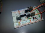
Every time I hook it up, there is ZERO response from the motor and the darlington transistors heat up to the point of smoking.

I have checked my wiring a million times but no luck.

See the attached pictures.


20131121_233755.jpg20131121_233725.jpg


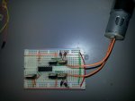
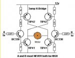
The two transistors closest to the motor are the tip122

the other two transistors are the tip127

the power is a 12v battery with a 5v regulator for the picaxe.


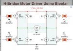
This is the schematic I was following: http://static.electro-tech-online.com/imgcache/3422-hbridge4IO.png

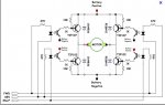
I have also tried this schematic with no luck: http://www.talkingelectronics.com/projects/200TrCcts/images101-200/H-Bridge-4.gif


my code for now is to just make the motor change direction every second


main:

high b.5
high c.1
low b.4
low c.0
pause 1000

low b.5
low c.1
high b.4
high c.0
pause 1000

goto main


I am not sure whether I should be turning on pin b.5+c.1 and b.4+c.0 on at the same time or vice versa, however I have tried both and neither work.


I am at a loss as to what I am doing wrong. Solutions would be greatly appreciated!
 

Hemi345

Senior Member
The circuit flows from one side to the other to 'turn' the motor, so you pull the bases high on one side and low on the other.

Code:
pause 2000

high c.0
high c.1
low b.4
low b.5

pause 2000

high b.5
high b.4
low c.0
low c.1
You're missing capacitors around the 7805 and decoupling on the PICAXE and motor.
 

Bill.b

Senior Member
The NPN and PNP transistors are in the wrong legs of the bridge.
also I think you will have trouble driving the PNP directly to full saturation with the picaxe.

It would help if you indicate which transistor you are diving with the picaxe outputs.

the second schematic with the optos would be the simplest to implement but an additional driver transistors
can be used.

hbridge.jpghbridge2.jpg

This unit would solve your problem and is only AU$9.00 (sorry do not have the pond symbol on my keyboard) It also includes the 5v regulator.

http://dx.com/p/l298n-stepper-motor-driver-controller-board-module-143633

Bill
 
Hi Bill, thanks for the response, the project is due soon, so I don't have time to order parts.
Your right, the motor moves a lot slower than it does directly connected to the battery. How would I drive the pnp transistor bases to increase the saturation?
I am assuming a transistor, but I'm not sure whether pnp or npn and how I would wire it?
The circuit I am using that works is this one: http://www.talkingelectronics.com/projects/200TrCcts/images101-200/H-Bridge-4.gif

but yeah the only issue I am having is not enough power is being sent to the motor as you guessed.
 

tony_g

Senior Member
Hi Bill, thanks for the response, the project is due soon, so I don't have time to order parts.
Your right, the motor moves a lot slower than it does directly connected to the battery. How would I drive the pnp transistor bases to increase the saturation?
I am assuming a transistor, but I'm not sure whether pnp or npn and how I would wire it?
The circuit I am using that works is this one: http://www.talkingelectronics.com/projects/200TrCcts/images101-200/H-Bridge-4.gif

but yeah the only issue I am having is not enough power is being sent to the motor as you guessed.

i am using a mosfet h bridge setup in one of my circuits and driving my motor from upto to 14v.

my high side(pnp) are being driven by two n channel fets from my picaxe at 5v.

i did this as the highside when pulled to off being high would feedback the higher voltage to the input pins and i didnt want to potentially kill the chip so this helped and allows me to run a lower voltage just for the 08m2 and a higher voltage for my motor.
 

Paix

Senior Member
With any H bridge versus direct connection to battery, then you will have a couple of junction drops to contend with, so will often need a slightly higher motor supply voltage to get a comparable voltage at the motor to compensate.

I think, but am not certain, that the drop is likely to be less when using FETs in the bridge.
 

AllyCat

Senior Member
Hi,

With any H bridge versus direct connection to battery, then you will have a couple of junction drops to contend with
Yes, with any "emitters inwards" configuration, in fact four junction drops if you're using Darlingtons (so perhaps 3 volts "lost").

However, the "emitters outwards" configuration shown by bill.b should lose only a couple of saturation drops (< 1 volt) particularly with the generously low resistor values (i.e. high current capability) shown. But, as the note says, it is vital to avoid the two sides being switched on at the same time, so the drive system should include some "dead space" between pulses.

Cheers, Alan.
 
Top