What size resistors? 4K7??
- Thread starter DocZaf
- Start date
That is correct, however they don't have to be 4.7k, they can generally be 2 to 10k.
See this specification for more details - page 39.
See this specification for more details - page 39.
westaust55
Moderator
See also PICAXE manual 2 (v7.8) page 79 which shows 4.7 kOhm resistors.
Can be worth looking in the three PICAXE manual sections for connection details for many simple/common devices in a PICAXE world.
4.7 kOhm is a good starting point.
Where higher bus speeds or longer bus wire lengths involved, a lower value can be recommended to help pull the clock and data lines back to a high state/level rapidly when released from a low state.
Last edited:
That has got to be a typo, as 7.7kR is NOT that common7.7 kOhm is a good starting point.
") Better stick with 4k7
Better stick with 4k7The I2C pull-up resistor values are a trade-off between power consumption and clock speed. To high a value will not allow the capacitance associated with the I2C lines to discharge at the specified rate,and the longer the tracks the greater the capacitance. If you need to use high values, then use the lowest I2C clock rate and keep the tracks as short as possible.
In practise, anything between 2.2K and 6.8K will work OK but it might be worth playing with different PICAXE speeds to check your not working 'on-the-edge'.
In practise, anything between 2.2K and 6.8K will work OK but it might be worth playing with different PICAXE speeds to check your not working 'on-the-edge'.
Hi again,
Gosh after reading all your replies it seems like its quite a complex affair....
The Eproms I will be using are 24LC512 which according to PicAxe manual is configured...
But I will no doubt have to have RTC somewhere and thats 100Khz
So I'm looking at i2Cslow and 10KOhn resistors then?
And Do i need capictors too?
As theyre none in the schematic?
Thanks Again,
DocZaf
[EDIT]
So the final design will be similar to the one in the "Using I2C with PicAxe" PDF
only difference being...
There will be two eproms and no speech module...
Using I2C PDF
Gosh after reading all your replies it seems like its quite a complex affair....
The Eproms I will be using are 24LC512 which according to PicAxe manual is configured...
Code:
24LC512 EE64kb
HI2CSetUp %1010dddx, i2cfast, i2cwordSo I'm looking at i2Cslow and 10KOhn resistors then?
And Do i need capictors too?
As theyre none in the schematic?
Thanks Again,
DocZaf
[EDIT]
So the final design will be similar to the one in the "Using I2C with PicAxe" PDF
only difference being...
There will be two eproms and no speech module...
Using I2C PDF
Last edited:
No, but the following capacitors are recommended: A decoupling capacitor for each IC in the circuit is recommended (100nF, across the power rails) plus one or more electrolytic capacitors - 100µF for battery supply, 100µF on output and input for linear regulator, 100µF on input and >470µF on output for switching regulator. Make that >1000µF on input if using rectified AC. You don't put capacitors on the data bus.And Do i need capictors too?
As theyre none in the schematic?
Hi again,
Gosh after reading all your replies it seems like its quite a complex affair....
No, as long as you are methodical and read the instructions on the tin then it is simple.
Whilst I agree with the good 'habits' of decoupling ICs like this with 100nF or so I'd be a little more careful than young Nick with regards to splattering capacitors with guessed values in other places.
As he says; don't put capacitors on the data line.
For regulators the best 'first best guess' wet capacitors is to READ the manufacturer's data sheet.
Position can be just as important as value / type.
Sometimes it comes down to the experience of Old Hacks.
If you want to get educated read this.
http://ww1.microchip.com/downloads/en/AppNotes/01028B.pdf
Then , in future, you can advise others on the Forum
Doczaf: Sorry if I have in any way contributed to the impression that I2C hardware is complex. In fact it could not be simpler. Just add two resistor as common pull-ups for all chips on the same I2C bus. The capacitance that I mention on the bus wiring is parasitic and you certainly don't want increase it with 'real' capacitors.
My first design
Hello all once again,
Thanks very much for all your help,
Having read all of the above...
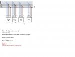
I have come up with the following circuit diagram....(see attached image)
Please dont laugh too much as i am very green in this area...
But trying my best....
Also...
Because I'm using the 28x2 module....
which comes with an external crystal...
and keeping in mind i want to access the data held in the eproms + I2C Ram as fast as possible...
Maybe I dont need to run at 100Khz but can use 400Khz?
(I came to this comclusion becuase i'm using an ext crystal an not the DS1307?)
Although I will still want to have a DS1307 connected for saving the actual time?
Thanks again,
DocZaf
Hello all once again,
Thanks very much for all your help,
Having read all of the above...
I have come up with the following circuit diagram....(see attached image)
Please dont laugh too much as i am very green in this area...
But trying my best....
Also...
Because I'm using the 28x2 module....
which comes with an external crystal...
and keeping in mind i want to access the data held in the eproms + I2C Ram as fast as possible...
Maybe I dont need to run at 100Khz but can use 400Khz?
(I came to this comclusion becuase i'm using an ext crystal an not the DS1307?)
Although I will still want to have a DS1307 connected for saving the actual time?
Thanks again,
DocZaf
Attachments
-
 25.1 KB Views: 29
Sorry Doc, I'm confused.
You asked about pull-up resistor values and in your somewhat unusual schematic you don't seem to have any apart from some mention of Point 6 Rp 1k5. What's all that about? Why can't you draw in exactly where resistors are meant to go?
Can you redraw it in the traditional way please. I can't remember pinouts.
Pen/ruler/paper/scan/photo(in focus) is fine if you don't have a drawing App.
And what's all that stuff saying Diodes??? LEDs?? at the bottom?
A bit of clarification would be appreciated.
And your final paragraph just sailed over my head
Updated circuit
Hiya Dippy,
Sorry for the shorct cut hahaha...
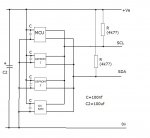
Okay here is the updated circuit again...
R1 and R2 are both 2.2K Ohms...
(I've amended this from 1.5K after re-reading page 6 of the the microchip document below...
Microchip PDF
C1 is 100nF Decoupling capactitor
C2 is 100uF Electrolytic capactitor
Please skip the bit about diodes and LED's
This was something else i was considering to give me a VISUAL confirmation that data was being transmitted/recieved...
Thanks for looking at my circuit and seeing if its correct at all and wether it can be optimised or modified for budget (not performance).
DocZaf
Hiya Dippy,
Sorry for the shorct cut hahaha...
Okay here is the updated circuit again...
R1 and R2 are both 2.2K Ohms...
(I've amended this from 1.5K after re-reading page 6 of the the microchip document below...
Microchip PDF
C1 is 100nF Decoupling capactitor
C2 is 100uF Electrolytic capactitor
Please skip the bit about diodes and LED's
This was something else i was considering to give me a VISUAL confirmation that data was being transmitted/recieved...
Thanks for looking at my circuit and seeing if its correct at all and wether it can be optimised or modified for budget (not performance).
DocZaf
Attachments
-
 22.3 KB Views: 23
BillyGreen1973
Senior Member
Hi, Doc.
I think you seem to have things a little confused and over complicated.
Check this layout, it should help make things a bit clearer.
As for the address pins on the EEPROMS etc. just tie them high or low directly so each device has a unique address.
Have a look at the Rev-Ed document for the 'I2C Tutorial' below.
http://www.picaxe.com/docs/axe110_i2c.pdf
I'm sorry Doc but that makes no sense to me.
I don't think you've grasped it... I certainly haven't
Why don't you look at the Data Logger schematic and see how you connect things up.
http://www.picaxe.com/docs/AXE110.pdf
Page 6.
I don't think you've grasped it... I certainly haven't
Why don't you look at the Data Logger schematic and see how you connect things up.
http://www.picaxe.com/docs/AXE110.pdf
Page 6.
To put it into simple words Doc -
Common all the SDA lines of ALL the devices, including the Picaxe.
Connect ONE pull-up resistor from this commoned SDA line to Vcc
Likewise common all the SCL lines of ALL the devices, including the Picaxe.
Connect ONE pull-up resistor from this commoned SCL line to VCC
Common all the SDA lines of ALL the devices, including the Picaxe.
Connect ONE pull-up resistor from this commoned SDA line to Vcc
Likewise common all the SCL lines of ALL the devices, including the Picaxe.
Connect ONE pull-up resistor from this commoned SCL line to VCC
Last edited: