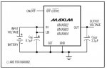
I thought I would close the loop on this regulator. My conclusion is that it is not a very good regulator. I rewired the circuit, but this time I added a 4.7K pullup to pin 1, LBO\, per the data sheet. I did not have this in my previous circuit. The output still reads 5.09V as before.
I think this conclusion is based upon expecting this very nice regulator to perform beyond its intended purpose. 5.09v is well within the published specification for this regulator.
When testing the OFF feature with a jumper to ground, the output slowly decays, taking of the order of 20-30 sec to get to 2.0V. However, if I remove the jumper after the output starts decaying, the output spikes to about 5.9V and then stabilizes at 5.09V. This is probably due to contact bounce.
If it takes that long to decay, then you are probably testing the output with "no load" other than your meter which is not a good testing method. You should have some kind minimum load on the output. If you look at the charts Maxim uses a 1K load resistor for most of their tests.
Moreover, the regulator will not latch off unless the output has decayed to around 0.5-1.0V before removing the active low sgnal. Reducing the output filter capacitor to 1uF shortens the off decay time as expected, but the regulator will not latch off with this value.
Again, with no load on the output, all bets are off.
Perhaps the 2.2uF datasheet specified capacitor is critical.
Not at all. The datasheets clearly states that 2.2uf is simply the minimum value.
From the Datasheet:
An output filter capacitor is required at the MAX882/MAX883/MAX884 OUT pin.
The minimum output capacitance required for stability is 2.2μF. The filter capacitor’s size
depends primarily on the desired power-up time and load-transient responses. Load-transient
response is improved by using larger output capacitors. The output capacitor’s equivalent
series resistance (ESR) will not affect stability as long as the minimum capacitance requirement
is observed. The type of capacitor selected is not critical, but it must remain above the minimum
value over the full operating temperature range.
So from the datasheet it is clear that transient response is actually improved by using a larger
output capacitor and that 2.2uf is the bare minimum for good regulation.
Another thing to consider from the datasheet is that this regulator is specifically designed for a battery
supply and that it is optimized for that.
From the datasheet:
The MAX882/MAX883/MAX884 are designed to
achieve low dropout voltages and low quiescent currents
in battery-powered systems. However, to gain these
benefits, the devices must trade away power supply
noise rejection, as well as swift response to supply
variations and load transients.....
That seems pretty clear. This device is not intended for used with a cheap wall wart as a supply or where
fast response to supply or load transients is needed.
This is just one of many regulators and not worth fooling with any longer.
For your particular application that may be true. However the Max883 can be a
very good choice for the applications that it was designed for.
 26.2 KB Views: 35