Voltage changes program execution-How

rogerm123

New Member
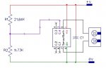
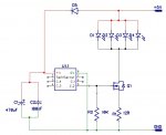
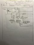
I am blinking three different color LED's from C.0,C.1 and C.2 (08M2). I am using a light detecting resistor to turn on start operation at dusk and turn off at dawn. Using 4 rechargeable batteries and a 5V solar charger panel. I do have a diode to prevent reverse drain back to solar panel.
Program ran consistent but not according to code. code ran fine on simulator. Finally hooked up to 3 1.5V batteries and ran fine. Discovered the 5.3V delivered to chip from rechargeable batteries vs 4.8V(weak batteries) changed program execution!! How can this be?
I had to put 2 more diodes prior to chip to get voltage down below 5V and is working fine now.
Comments?
 

PhilHornby

Senior Member
We probably need to see the schematic and the code - Also an indication of what was actually happening...
 

john2051

New Member
Personally I prefer to keep the voltage slightly on the low side (4.9v) It doesn't take much of a pulse at 5.3v to do permanent damage.
 

rogerm123

New Member
See attached program below. I do have a grounding 10k resistor tied to C.5 and also to C.0,C.1, and C.2 output as these three drive MOSFET's. I am only supplying a 12 ohm resistor for the LED's as the blink duration is short (pause 30) and i want them as bright as possible without shortening their life too much. I would attach a schematic but I have not created one yet- but can if need be.
First time using a solar panel and I am learning that a rating of 5V is nominal? In bright sun it is more and I suppose in dim sun it falls lower?
 

Attachments

PhilHornby

Senior Member
I would attach a schematic but I have not created one yet- but can if need be.
A hand-drawn diagram, photographed by your 'phone will suffice.
See attached program below.
It probably makes it a bit easier for people, if you insert it inline:-
Code:
symbol WMos = C.0
symbol RMos = C.1
symbol BMos = C.2
symbol RanNo = w0
symbol lastDig = b0
symbol Vin=b2
symbol ctr=b1
symbol ctr2=b3
;60,000=60sec,1000=1sec, cant go over 60 sec in pause

Start:
    ctr2=1
    ctr=1
    ;goto Runn
    goto ckDaylight

ckDaylight:
    readadc c.4,Vin
        if Vin<220 then
            disablebod
            sleep 782 ;782=30min
            enablebod
            goto ckDaylight
        end if
   
        If Vin>=250 then
            ctr2=1
            ctr=1
            goto Runn
        end if

Runn:     
        pause 7000;7sec
       
        if ctr2>150 then ;300
            goto ckDaylight
        end if
        if ctr>10 then
            ctr=1
        end if
        if ctr=1 then
            GoTo FlashWRB
        end if
        if ctr=2 then
            GoTo FlashB
        end if
        if ctr=3 then
            GoTo FlashWWW
        end if
        if ctr=4 then
            GoTo FlashWB
        end if
        if ctr=5 then
            GoTo FlashRRR
        end if
        if ctr=6 then
            GoTo FlashW
        end if
        if ctr=7 then
            GoTo FlashBBB
        end if
        if ctr=8 then
            GoTo FlashWR
        end if
        if ctr=9 then
            GoTo FlashRB
        end if
        if ctr=10 then
            GoTo FlashR
        end if
  
    goto Runn

FlashWRB:
    'do timing and flash WRB
    High WMos
    pause 30;
    low WMos
    pause 600;
    high RMos
    pause 30
    low RMos
    pause 600
    high BMos
    pause 30
    low BMos
    ctr=ctr+1
    ctr2=ctr2+1
    goto Runn

FlashB:
    High BMos
    pause 30;
    low BMos
   
    ctr=ctr+1
    ctr2=ctr2+1
    goto Runn
   
FlashWWW:
    'do timing and flash WRB
    High WMos
    pause 30;
    low WMos
    pause 600;
    high WMos
    pause 30
    low WMos
    pause 600
    high WMos
    pause 30
    low WMos
    ctr=ctr+1
    ctr2=ctr2+1
    goto Runn
   
FlashWB:
    'do timing and flash WRB
    High WMos
    pause 30;.288 sec
    low WMos
    pause 600; .072 sec
   
    high BMos
    pause 30
    low BMos
    ctr=ctr+1
    ctr2=ctr2+1
    goto Runn
   
FlashRRR:
    'do timing and flash WRB
    High RMos
    pause 30;.288 sec
    low RMos
    pause 600; .072 sec
    high RMos
    pause 30
    low RMos
    pause 600
    high RMos
    pause 30
    low RMos
    ctr=ctr+1
    ctr2=ctr2+1
    goto Runn

FlashW:
    'do timing and flash WRB
    High WMos
    pause 30;.288 sec
    low WMos
   
    ctr=ctr+1
    ctr2=ctr2+1
    goto Runn

FlashBBB:
    'do timing and flash WRB
    High BMos
    pause 30;.288 sec
    low BMos
    pause 600; .072 sec
    high BMos
    pause 30
    low BMos
    pause 600
    high BMos
    pause 30
    low BMos
    ctr=ctr+1
    ctr2=ctr2+1
    goto Runn

FlashWR:
    'do timing and flash WRB
    High WMos
    pause 30;.288 sec
    low WMos
    pause 600; .072 sec
    high RMos
    pause 30
    low RMos
   
    ctr=ctr+1
    ctr2=ctr2+1
    goto Runn

FlashRB:
    'do timing and flash WRB
   
    high RMos
    pause 30
    low RMos
    pause 600
    high BMos
    pause 30
    low BMos
    ctr=ctr+1
    ctr2=ctr2+1
    goto Runn

FlashR:
    'do timing and flash WRB
  
    high RMos
    pause 30
    low RMos
   
    ctr=ctr+1
    ctr2=ctr2+1
    goto Runn
 

Technical

Technical Support
Staff member
Did you previously make use of this?
symbol RanNo = w0

If so it will have clashed with, and corrupted, both b0 and b1.
 

rogerm123

New Member
Did you previously make use of this?
symbol RanNo = w0

If so it will have clashed with, and corrupted, both b0 and b1.
Yes I did but could not get it to work. However, after I aborted using RanNo it performed as it should. Also recently I even switched the original chip out. It hits on the FlashWR every cycle versus another combination. I can hook up to a 4.8V supply and it sequences as the code reads-correctly.
 

PhilHornby

Senior Member
The Mosfet Drains are presumably connected to +ve in real life? ;)

What about those Mosfet gates, are they really all connected together, then to a single 10K resistor? That arrangement would try to turn them all on together, but would probably damage the Picaxe instead (because all the outputs would all be shorted together as well) :(
 

Buzby

Senior Member
That circuit as drawn will never work, for the reasons Phil has mentioned.

However, assuming that the circuit around the LDR is correctly drawn, then the code will behave differently as the supply voltage changes.

Imagine the LDR is held at a steady value, but the supply voltage increases. As the supply increases, the voltage at the PICAXE pin will increase accordingly, even though the resistance of the LDR hasn't changed. It's an example of a simple voltage divider, voltage out = supply / ratio of resistors.

You need to have the +ve end of the 20K at a fixed voltage, which needs to be lower than the lowest expected supply. A simple Zener diode circuit, maybe 3.3v, would stabilise the voltage to the 'top end' of the 20K/LDR circuit.
 

rogerm123

New Member
Thanks all- I drew the circuit wrong. Each mosfet gate is connected straight to its own output pin. Also, considering stabilizing the voltage to the LDR; I am thinking about just purchasing a voltage regulator card to supply 5V or 3V from batteries to run everything but the LED's. Any comments on that?

I know at 4.5V all works as intended.
I know at 5.3V it only executes FlashWR (and that is confirmed at the chip pin outputs- not at the LED's)
 

PhilHornby

Senior Member
I had a go at reformatting the code to improve readability.

See what you think...

Rich (BB code):
#picaxe 08m2
#no_data

symbol WMos = C.0
symbol RMos = C.1
symbol BMos = C.2

symbol Vin=b2
symbol ctr=b1
symbol ctr2=b3
;60,000=60sec,1000=1sec, cant go over 60 sec in pause

Start:
;     ctr2=1
      ctr=1

      low Wmos,RMos,Bmos                        ;turn off Mosfets (by setting their Gates LOW

      do    
            do
                  readadc c.4,Vin               ;The darker it is, the higher voltage
                  if Vin<220 then
                        disablebod
                        sleep 782 ;782=30min
                        enablebod
                  end if
            
            loop while Vin < 220

            If Vin>=250 then                    ;?
                  ;ctr2=1
                  ctr=1 
            end if
            
            for ctr2 = 1 to 150                 ;repeat sequence 150 times, before rechecking for daylight
                  
                  pause 7000                    ;7sec
                  
                  select case ctr
                        ;
                        ; Activate correct 'pattern'
                        ;
                        case 1
                              'do timing and flash WRB
                              pulsout Wmos,30
                              pause 600; 
                              pulsout Rmos,30
                              pause 600
                              pulsout Bmos,30
                  
                        case 2
                              Pulsout Bmos,30   
                  
                        case 3
                              'do timing and flash WRB
                              Pulsout Wmos,30
                              pause 600; 
                              Pulsout Wmos,30
                              pause 600
                              Pulsout Wmos,30

                        case 4
                              'do timing and flash WRB
                              Pulsout Wmos,30
                              pause 600; .072 sec
                              pulsout Bmos,30

                        case 5
                              'do timing and flash WRB
                              Pulsout Rmos,30
                              pause 600; .072 sec
                              Pulsout Rmos,30
                              pause 600
                              Pulsout Rmos,30
                        
                        case 6
                              'do timing and flash WRB
                              Pulsout Wmos,30

                        case 7
                              'do timing and flash WRB
                              Pulsout Bmos,30
                              pause 600; .072 sec
                              Pulsout Bmos,30
                              pause 600
                              Pulsout Bmos,30
                              
                        case 8
                              'do timing and flash WRB
                              Pulsout Wmos,30
                              pause 600; .072 sec
                              Pulsout Rmos,30
                              
                        case 9
                              'do timing and flash WRB
                              pulsout Rmos,30
                              pause 600
                              Pulsout Bmos,30
                        
                        case 10
                              'do timing and flash WRB
                              pulsout Rmos,30
                  
                  end select

                  inc ctr                       ;next 'pattern'
                  
                  if ctr>10 then                ;repeat pattern 10 times
                        ctr=1                   ;then restart
                  end if
            
            next ctr2
      loop                                      ;time to recheck for daylight
 

PhilHornby

Senior Member
I am thinking about just purchasing a voltage regulator card to supply 5V or 3V from batteries to run everything but the LED's. Any comments on that?
The voltage regulator could well become the biggest drain on the batteries...

Another approach would be to measure the supply rail voltage and then consider the LDR voltage as a percentage of that, rather than an absolute value.
 

AllyCat

Senior Member
Hi,
... assuming that the circuit around the LDR is correctly drawn, then the code will behave differently as the supply voltage changes.
Actually, that's one of the (few) parts of the concept that should work. The ADC is "ratiometric" (i.e. it uses the supply rail as Reference) so the ADC measurements should "track" with a voltage divider connected across the (PICaxe's) supply rail. It's the PICaxe's "TTL" digital input thresholds that remain moderately constant with supply voltage variations, but the variation in light levels is so enormous that almost any configuration should be able to differentiate Day from Night. ;)

But where to start? Firstly, the schematic diagram does not show a decoupling capacitor across the supply rail (close to Legs 1 and 8), but the PIC(axe) appears to become progressively more sensitive to "noise" on the supply rail as the voltage rises. It's nearly always worthwhile to put a #terminal 4800 and SERTXD("Starting",CR,LF) at the very start of every program to check if the program "unexpectedly" reboots/restarts for any reason (hardware or software). Personally, I usually insert a simple CALIBADC... routine to report the actual supply voltage, which can often predict "unexpected" malfunctioning when the supply battery reaches the end of its charge.

IMHO, the use of 4 (NiMH) cells is somewhat problematic; the voltage across a fully-charged NiMH cell is 1.5 volts, so four could deliver 6 volts across the PICaxe and the PV panel will need to deliver at least 6.5 volts via the (probably necessary) series diode (BTW is that a Schottky diode symbol ? - they're often considered to be rather "leaky"). PV panels are primarily "constant voltage" but the (maximum) available current is proportional to the amount of solar energy falling on the panel. Each "segment" of the panel is effectively a forward-biassed silicon diode which delivers approximately 0.5 volts, so you may be able to estimate the maximum voltage by inspection. Note that this voltage falls by about 2/600 (mV) per degree C ,or about -1% for each 3 degrees C (5 degrees F) rise in temperature. PV panels can get quite hot!

Personally, I would probably use 3 x NiMH cells (or a single Lithium Poly rechargeable is much the same) applied directly to the PICaxe. Then the PICaxe can monitor the voltage (as in para 2 above) and can even increase the drain/load on the battery if/when it is reaching full charge. There is very rarely any justification for using the DISABLEBOD command; it saves very little power (a few microamps) and the primary purpose of the Brownout Detector is to ensure that the PIC(axe) does recover correctly when (re-) starting from an "unreliable" supply.

Finally, Phil has saved me the effort to show how the program can be simplified and I suspect the addition of a couple of Subroutines or Macros could do even more. Similarly, an auxiliary power converter/regulator may raise more issues than it solves.

Cheers, Alan.
 

Buzby

Senior Member
DISABLEBOD is a very risky function.

When active it allows the chip to run at well below the normal supply voltage, but it's not a simple to use as it sounds.

Running at a very low voltage risks the chip misbehaving in unexpected ways if the supply varies. These can include memory corruption and peripheral glitches. It's really only useful for running with a stable and reliable low voltage supply, and as Alan has said, enabling the BOD ensures proper start-up and shut-down behavior. The tiny power saving it offers is not worth the risk.

In fact, I don't know why Rev-Ed even included it in the command set. It's more trouble than its worth.
 

PhilHornby

Senior Member
Actually, that's one of the (few) parts of the concept that should work. The ADC is "ratiometric" (i.e. it uses the supply rail as Reference) so the ADC measurements should "track" with a voltage divider connected across the (PICaxe's) supply rail.
I must say I've never used the ADC without also using the FVR, so I thought @Buzby's point was valid. I've clearly always skipped over the concept of using the supply rail as the reference and don't quite see how it works :unsure:. I'll breadboard something and educate myself :)

But, accepting that isn't the problem, then what is ❓

I know at 4.5V all works as intended.
I know at 5.3V it only executes FlashWR (and that is confirmed at the chip pin outputs- not at the LED's)
(That's case 8 in my code above).
 

Buzby

Senior Member
I'd never considered that the ADC was ratiometric with respect to the supply voltage. If that is the case, then the ADC value should not change when the supply voltage changes. Phil's forthcoming experiments should prove it one way or the other.

If it is ratiometric then the effect the OP is seeing must be due to something else. My money is on decoupling capacitors, weak PSU conditions, or a wiring problem.
 

hippy

Technical Support
Staff member
But, accepting that isn't the problem, then what is ❓
It does seem odd.

While the ADC is ratiometric, perhaps that's not so guaranteed when the supply voltage is above recommended. Maybe the voltage reference is capping out at some level lower than the voltage across the LDR divider ? That could be perceived as the ADC input rising while the ADC reference stands still.

Just speculation rather than tested and I haven't studied the intention of the code.
 

PhilHornby

Senior Member
OK I tried a simple readadc c.4,Vin in a loop (with a one second pause.)

Readadc.jpg

The value returned was 78±1. This was consistent over a supply voltage range of 2.5V to 6V.

Disconnecting R1 gave the expected value of 0 and disconnecting R2 gave 255).

("78" equates to the voltage at the divider network, if the supply was 255V).

So it works as @Alleycat said (y)
 

rogerm123

New Member
I appreciate all the detail recommendations all are giving. I for sure will incorporate the cleaned up code. Also since sucking solder and re soldering kind of SUCKS; I took one of above's advice and rewired to run the chip and everything associated with it on 3 batteries(4.2V). I left the MOSFET's source tied to the 4 batteries (5.5V), 5.2 V after diode. Works as intended now but may not be robust over time. Noticed it may come on at a higher light level at dusk but if that is a problem I am thinking I can adjust the ADC Vin argument value.
Since I will be making a couple more of these, I have gleaned some good advice from ALL that I will be trying to incorporate. I will research on calibration routines.
Note, this is just a nocturnal predator deterrent device which just has to come on when it gets dark, flash the lights as programmed, and cut off at daybreak.

Thanks
 

inglewoodpete

Senior Member
I used an LDR on a 14M2 to make a crude 24-hour clock for controlling the lighting display on the fascade of the multistorey building. It has been operating for over 9 years now. The software samples and stores the light level every minute, storing the last 20 values in the available RAM (arranged as a circular buffer). It then takes an average of the buffer values every minute to determine dusk and dawn. From those values it determines the middle of the night and calculates the approximate time to switch off the lighting display (if my memory serves me correctly, 11:00PM). Using the system TIME variable, the free running 14M2 was typically accurate to 3 minutes/day = 3/1440 or 0.2% when I last tested it.
 
Last edited:

rogerm123

New Member
I wanted to report back that I finally had a chance to get my blinker back on the table; one, because when I dropped the voltage to the 08M2 chip it dropped the voltage to the MOSFET gate as well and I am thinking gate voltage influences current flow-thus not as bright a LED flash; second, because I had a cow that wanted to play with it and damaged it.

I installed the 100nF capacitor across the supply to the 08M2 and switched the supply back to the 5.4V and seems to work now.
Thanks again for all the help.
 

PhilHornby

Senior Member
Can't help with the cow ... the last one I had to deal with - blocking my path in the middle of Exmoor - responded only to my motorcycle being revved to 10,000rpm. Flashing my headlamp did nothing :)

How about modifying the circuit, something like this :-

25910

Having the LEDs on the 'high' side should alleviate your voltage drop problem. You can still set the current using R1. The addition of D5 and C1 are to try and stop the LEDs making the supply to the Picaxe droop.
 
Last edited:

rogerm123

New Member
Not been to that part of England but pics are beautiful.

How did you come up with the value of C1-experience? Why would you need C2 then as it would be overshadowed by C1? Note I did not use electrolytic capacitors-does that matter? Also testing on the breadboard the MOSFET gate drained off quick enough through the 08M2 so I did not include R2-should I go back and install?
Overall I understand what you have proposed though and will try to incorporate.
Thanks
 

PhilHornby

Senior Member
C1 - guesswork ;) and will have to be electrolytic, given its size.

C2 is to filter high frequency glitches. Something I've wondered for 50+ years, is why you need two. Everyone knows the resulting capacitance is just the sum of the two, so the tiny one should make no difference! I assume it's to do with ESR and other such effects. Maybe someone will come along and explain it. I gave up pondering and just accept it :)

R2 is just 'for completeness' and is probably not necessary. When the circuit powers on, the pins driving the MOSFET(s) will be inputs and so high impedance. With nothing tying the gate to ground, the LEDS may all give a brief 'flash'. I suppose given the number of them, that sudden drain on the battery could contribute to upsetting the Picaxe, even though it only lasts a few milliseconds.

There is still a potential issue regarding the use of LEDS in parallel. But if they're working, we should move swiftly on!

Some interesting info HERE regarding MOSFETs.
 

inglewoodpete

Senior Member
How did you come up with the value of C1-experience? Why would you need C2 then as it would be overshadowed by C1? Note I did not use electrolytic capacitors-does that matter? Also testing on the breadboard the MOSFET gate drained off quick enough through the 08M2 so I did not include R2-should I go back and install?
C1 reduces switching noise created inside the PIC - all digital circuitry creates switching noise which appears on the power pins. Electrolytic capacitors do not respond well to these high frequencies created by switching noise. Instead, C2 acts as an energy reserve, keeping the power rail steady in all circumstances.

When the PICAXE boots up, its I/O pins are all initialised as inputs. With pin C.2 set to high impedance (Ie as an input) the MOSFET's gate can randomly switch on at power-up. R2 holds the MOSFET's gate in a low state, ensuring that the MOSFET is in the 'off' state at boot-up. If the MOSFET is not switching on fully, replace it with one designed for logic level use.
 

AllyCat

Senior Member
Hi,

If you want to increase the current in the LED(s) then put R1 in series with the Source of the FET and not the Drain. Then the voltage drop across R1 won't reduce the Vgs to the FET. If the supply really is "5 volts" (i.e. less than 5.5 max) then personally I wouldn't bother with D5 or C1 (unless the supply has an unusually high source impedance). In an "emitter-follower" (i.e. bipolar transistor) type of configuration, the resistor is intended to reduce and stabilise the current gain. Less effective with a FET because the Vgs is usually more (and more variable) than the Vbe of a bipolar transistor.

Electrolytic capacitors normally have significant series inductance because they are typically of a "wound" construction of aluminium foil. That makes them less efficient as a capacitor at very high frequencies (e.g. of digital logic circuits). There is the possibility that in some circumstances they may add some useful "damping" to reduce the risk of the "small" (ceramic) decoupling capacitor becoming series resonant with the stray inductance of "long" PCB tracks. Series resonance causes an increase in impedance, thus reducing the effectiveness of a capacitor for decoupling (parallel resonance lowers the impedance of a network).

Cheers, Alan.
 
Last edited:

rogerm123

New Member
Good stuff. All of you are teaching me a lot. I think one of the most important thing is to always use good design practices to increase the robustness. I will incorporate Logic Level MOSFET's instead of power MOSFET's. I now understand the stray LED blip on start up that is not associated with the program.
 
Top