VARIOMETER using GY63/MS5611 barometer

Benjie

Senior Member
Hello,
first let me wish to everybody a merry Christmas.
Now let me come to my project: Hippy helped me a lot with coding the barometer coding on a 08M2. it is almost working except the sensitivity which is somewhat erratic.
The code was written by Hippy but I simplified it just to read the pressure. Being interested to transmit down to ground the pressure variations (positive or negative) to assess if a model glider is ascending or descending,
The final code will read the pressure, store the value in a word, wait one second and loop back to compare the stored value with the new one. the result will generate a sound which frequency will depend on the difference of the two words. The information will be radio transmitted to ground.
The problem I am facing is the interpretation of the pressure readings.
Hippy helped me a lot with the barometer coding on a 08M2. it is almost working except the resolution which is not adequate on word Ph alone.
The code is:
Code:
#Picaxe 08M2
#Terminal 4800
#No_Data

Symbol C0 = w1  : Symbol C0.msb = b3  : Symbol C0.lsb = b2
Symbol C1 = w2  : Symbol C1.msb = b5  : Symbol C1.lsb = b4
Symbol C2 = w3  : Symbol C2.msb = b7  : Symbol C2.lsb = b6
Symbol C3 = w4  : Symbol C3.msb = b9  : Symbol C3.lsb = b8
Symbol C4 = w5  : Symbol C4.msb = b11 : Symbol C4.lsb = b10
Symbol C5 = w6  : Symbol C5.msb = b13 : Symbol C5.lsb = b12
Symbol C6 = w7  : Symbol C6.msb = b15 : Symbol C6.lsb = b14
Symbol C7 = w8  : Symbol C7.msb = b17 : Symbol C7.lsb = b16

Symbol Pl = w9  : Symbol Pl.msb = b19 : Symbol Pl.lsb = b18
Symbol Ph = w10 : Symbol Ph.msb = b21 : Symbol Ph.lsb = b20

'Symbol Tl = w11 : Symbol Tl.msb = b23 : Symbol Tl.lsb = b22
'Symbol Th = w12 : Symbol Th.msb = b25 : Symbol Th.lsb = b24

Symbol CMD_RESET   = $1E
Symbol CMD_D1_256  = $40
Symbol CMD_D1_512  = $42
Symbol CMD_D1_1024 = $44
Symbol CMD_D1_2048 = $46
Symbol CMD_D1_4096 = $48

'Symbol CMD_D2_256  = $50
'Symbol CMD_D2_512  = $52
'Symbol CMD_D2_1024 = $54
'Symbol CMD_D2_2048 = $56
'Symbol CMD_D2_4096 = $58
Symbol CMD_ADC     = $00
Symbol CMD_PROM_0  = $A0
Symbol CMD_PROM_1  = $A2
Symbol CMD_PROM_2  = $A4
Symbol CMD_PROM_3  = $A6
Symbol CMD_PROM_4  = $A8
Symbol CMD_PROM_5  = $AA
Symbol CMD_PROM_6  = $AC
Symbol CMD_PROM_7  = $AE

PowerOnReset:

  HI2cSetup I2CMASTER, %11101110, I2CSLOW, I2CBYTE

  HI2cOut ( CMD_RESET )
  Pause 10

  HI2cOut ( CMD_PROM_0 ) : HI2cIn ( C0.msb, C0.lsb )
  HI2cOut ( CMD_PROM_1 ) : HI2cIn ( C1.msb, C1.lsb )
  HI2cOut ( CMD_PROM_2 ) : HI2cIn ( C2.msb, C2.lsb )
  HI2cOut ( CMD_PROM_3 ) : HI2cIn ( C3.msb, C3.lsb )
  HI2cOut ( CMD_PROM_4 ) : HI2cIn ( C4.msb, C4.lsb )
  HI2cOut ( CMD_PROM_5 ) : HI2cIn ( C5.msb, C5.lsb )
  HI2cOut ( CMD_PROM_6 ) : HI2cIn ( C6.msb, C6.lsb )
  HI2cOut ( CMD_PROM_7 ) : HI2cIn ( C7.msb, C7.lsb )

MainLoop:
do

    HI2cOut ( CMD_D1_4096 )
    Pause 10
    HI2cOut ( CMD_ADC )
    Pause 10

    HI2cIn ( Ph.msb, Ph.lsb, Pl.msb, Pl.lsb)
    sertxd(#Ph,"   ",#Pl.msb,"    ",# Pl.lsb,cr,lf)
    
pause 100        
 Loop
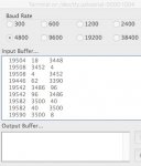
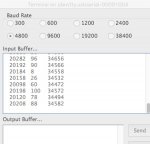
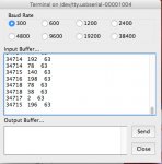
The terminal output is:

The Word Ph is ok but the meaning of Word PI is difficult to understand (see the attached terminal picture)
Hippy can you or someone else help
 

Attachments

hippy

Technical Support
Staff member
You are reading a signed 24-bit value and storing that in three bytes; ph.msb, ph.lsb and pl.msb

You are then showing ph as a 16-bit integer word, plus pl.msb and pl.lsb as 8-bit integer bytes.

pl.lsb, the third column, those "63" values, should be ignored.

The signed 24-bit values your numbers represent are as follows -
Code:
.---------------------------------.
| nmlk jihg fedc ba98   7654 3210 |---------------.
`---------------------------------'               |
.---------------------.---------------------.     |
| nmlk jihg fedc ba98 | 7654 3210 ---- ---- |     |
`----------.----------^-----.---------------'     |
  .--------'                |                     |
  |    .--------------------'                     |
  |    |          .-------------------------------'
__|__ _|_      ___|___
34714 192  =  -7890240
34714 78   =  -7890354
34715 140  =  -7890036
34716 198  =  -7889722
34718 78   =  -7889330
34718 38   =  -7889370
34717 2    =  -7889662
34715 196  =  -7889980
I guess that is what you are reading with the sensor sitting immobile on a table ?

The problem isn't so much what the numbers themselves mean but what values you get at various heights.

You need to know what range of values you will be dealing with before you can decide how best to handle them, what calculations you would need to apply to get the tone change you want which represents a change in height.

You can either determine the value by experimentation or by performing the pressure calculations detailed in the datasheet for the pressures you would likely expect.

Unfortunately, with the limited data we have, it is like walking into a room and saying "forty two" and trying to go from there. That 42 is meaningless without some appropriate context.
 
Last edited:

Benjie

Senior Member
Thank you Hippy for the fast reply.
Can you tell me how you convert the second column to the =xxxx column?
The acceptable resolution would be to get up to the forth digit af the 3rd column.
I am not very concerned with the span of the pressure because the differential will not exceed 200 meters.
 

hippy

Technical Support
Staff member
The signed 24-bit number value read can be manually calculated by -

read value = ( ph * 256 ) + pl.msb

But that cannot be done on a PICAXE without causing overflow.

An alternative approach, if you are mostly interested in the least significant bits, is to read the raw input bytes so the lsb aligns with pl.lsb rather than aligning the msb with ph.msb as you currently are doing.

That would be -
Code:
MainLoop:
do

    HI2cOut ( CMD_D1_4096 )
    Pause 10
    HI2cOut ( CMD_ADC )
    Pause 10

    HI2cIn ( Ph.lsb, Pl.msb, Pl.lsb) : Ph.msb = 0
    sertxd(#Ph,"   ",#Pl,cr,lf)
    
    pause 100        
Loop
With the previous data you would have displayed -
Code:
          .---------------------------------.
          | nmlk jihg   fedc ba98 7654 3210 |-----.
          `---------------------------------'     |
.---------------------.---------------------.     |
| ---- ---- nmlk jihg | fedc ba98 7654 3210 |     |
`----------.----------^----------.----------'     |
 .---------'                     |                |
 |    .--------------------------'                |
 |    |           .-------------------------------'
_|_ __|__      ___|___
135 39616  =  -7890240
135 39502  =  -7890354
135 39820  =  -7890036
135 40134  =  -7889722
135 40526  =  -7889330
135 40486  =  -7889370
135 40194  =  -7889662
135 39876  =  -7889980
 

Benjie

Senior Member
I have been playing with the Pl.msb which displayed on sertxd some meaningful variation when moving the sensor up and down on a lift. To asses its functionality I added a piece of code to trigger two led's.
Code:
do

    HI2cOut ( CMD_D1_4096 )
    Pause 10
    HI2cOut ( CMD_ADC )
    Pause 10

    HI2cIn ( Ph.lsb, Pl.msb, Pl.lsb) : Ph.msb = 0
   sertxd(#Pl.msb,"   ",#Pl.lsb,cr,lf)

 if  Pl.msb < w11 then 
     low 4    
 elseif Pl.msb > w11 then
     low 0
 endif  
 W11 = Pl.msb
high 0
high 4
   pause 100
The result is still unsatisfactory.
A variometer using the same sensor but controlled by a Arduino nano exists. The description and the code can be viewed at "https://www.rcgroups.com/forums/showthread.php?1749208-DIY-simple-and-inexpensive-Arduino-based-sailplane-variometer".
I mind if someone in the forum can read (explain) the Arduino code listed in the RC groups forum.
Just understanding it may greatly help its conversion to Picaxe.
Unfortunately I am totally unable to get a clue out of Arduino code while I have quite a good experience in designing a radio link.

Any volunteer?
 

hippy

Technical Support
Staff member
I mind if someone in the forum can read (explain) the Arduino code listed in the RC groups forum.
The example code reads the raw sensor data, converts it to an actual pressure value using the configuration values.

It then determines whether the pressure value has increased or decreased since the last reading, and creates a slower changing version of that, so minor changes in altitude are damped out.

It then uses that damped out change in altitude to produce a tone which reflects how quickly or slowly any change is occurring.

Just understanding it may greatly help its conversion to Picaxe.
I don't understand exactly how it's doing it because it uses two slower changing versions of the changes. But the general principle is understandable. The rest is just tweaking to 'make it better'.

The problem in converting that for a PICAXE is it uses actual pressure values while we are just using raw values, and the PICAXE cannot easily deal with signed floating point values which it uses.

The result is still unsatisfactory.
In what way ? What do you want to happen ? What does it actually do ?

It could be that you're just not handling the LED's very well.

I would start with the code below which reports the changes in Pl. That can be adjusted to affect the LED's if you can describe what they indicate and how they are wired.
Code:
Symbol Xl = w11
Symbol Dl = w12

MainLoop:
do

    HI2cOut ( CMD_D1_4096 )
    Pause 10
    HI2cOut ( CMD_ADC )
    Pause 10

    HI2cIn ( Ph.lsb, Pl.msb, Pl.lsb) : Ph.msb = 0

    Select Case Pl
      Case > Xl
        Dl = Pl - Xl
        SerTxd( #Xl, TAB, "-> ", #Pl, TAB, "+", #Dl, CR,LF ) 
      Case < Xl
        Dl = Xl - Pl
        SerTxd( #Xl, TAB, "-> ", #Pl, TAB, "-", #Dl, CR,LF ) 
      Else
        Dl = 0
        SerTxd( #Xl, TAB, "-> ", #Pl, TAB, "=", #Dl, CR, LF )
    End Select

    Xl = Pl
   
    pause 500
Loop
 
Last edited:

Benjie

Senior Member
Here is how I drive two led's to indicate an increase or a decrease of the pressure at half second time interval.
Code:
#Picaxe 08M2
#Terminal 4800
#No_Data

Symbol C0 = w1  : Symbol C0.msb = b3  : Symbol C0.lsb = b2
Symbol C1 = w2  : Symbol C1.msb = b5  : Symbol C1.lsb = b4
Symbol C2 = w3  : Symbol C2.msb = b7  : Symbol C2.lsb = b6
Symbol C3 = w4  : Symbol C3.msb = b9  : Symbol C3.lsb = b8
Symbol C4 = w5  : Symbol C4.msb = b11 : Symbol C4.lsb = b10
Symbol C5 = w6  : Symbol C5.msb = b13 : Symbol C5.lsb = b12
Symbol C6 = w7  : Symbol C6.msb = b15 : Symbol C6.lsb = b14
Symbol C7 = w8  : Symbol C7.msb = b17 : Symbol C7.lsb = b16

Symbol Pl = w9  : Symbol Pl.msb = b19 : Symbol Pl.lsb = b18
Symbol Ph = w10 : Symbol Ph.msb = b21 : Symbol Ph.lsb = b20

'Symbol Tl = w11 : Symbol Tl.msb = b23 : Symbol Tl.lsb = b22
'Symbol Th = w12 : Symbol Th.msb = b25 : Symbol Th.lsb = b24

Symbol CMD_RESET   = $1E
Symbol CMD_D1_256  = $40
Symbol CMD_D1_512  = $42
Symbol CMD_D1_1024 = $44
Symbol CMD_D1_2048 = $46
Symbol CMD_D1_4096 = $48

'Symbol CMD_D2_256  = $50
'Symbol CMD_D2_512  = $52
'Symbol CMD_D2_1024 = $54
'Symbol CMD_D2_2048 = $56
'Symbol CMD_D2_4096 = $58
Symbol CMD_ADC     = $00
Symbol CMD_PROM_0  = $A0
Symbol CMD_PROM_1  = $A2
Symbol CMD_PROM_2  = $A4
Symbol CMD_PROM_3  = $A6
Symbol CMD_PROM_4  = $A8
Symbol CMD_PROM_5  = $AA
Symbol CMD_PROM_6  = $AC
Symbol CMD_PROM_7  = $AE

PowerOnReset:

  HI2cSetup I2CMASTER, %11101110, I2CSLOW, I2CBYTE

  HI2cOut ( CMD_RESET )
  Pause 10

  HI2cOut ( CMD_PROM_0 ) : HI2cIn ( C0.msb, C0.lsb )
  HI2cOut ( CMD_PROM_1 ) : HI2cIn ( C1.msb, C1.lsb )
  HI2cOut ( CMD_PROM_2 ) : HI2cIn ( C2.msb, C2.lsb )
  HI2cOut ( CMD_PROM_3 ) : HI2cIn ( C3.msb, C3.lsb )
  HI2cOut ( CMD_PROM_4 ) : HI2cIn ( C4.msb, C4.lsb )
  HI2cOut ( CMD_PROM_5 ) : HI2cIn ( C5.msb, C5.lsb )
  HI2cOut ( CMD_PROM_6 ) : HI2cIn ( C6.msb, C6.lsb )
  HI2cOut ( CMD_PROM_7 ) : HI2cIn ( C7.msb, C7.lsb )

MainLoop:

do

    HI2cOut ( CMD_D1_4096 )
        Pause 10
    HI2cOut ( CMD_ADC )
        Pause 10

    HI2cIn ( Ph.lsb, Pl.msb, Pl.lsb) : Ph.msb = 0
       sertxd(#Pl.msb,"   ",#Pl.lsb,cr,lf)
       
     if  Pl.msb < w11 then 
         low 4    
     elseif Pl.msb > w11 then
         low 0
     elseif Pl.msb = W11 then exit
     endif  
 W11 = Pl.msb
    high 0
    high 4 
 pause 500
 Loop
 

hippy

Technical Support
Staff member
Here is how I drive two led's to indicate an increase or a decrease of the pressure at half second time interval
But what is each LED meant to indicate and how are they wired to the PICAXE ?

If what you have is unsatisfactory because you are controlling the LED's in an inappropriate manner it is impossible to say what a better way would be without knowing that information.

Do you have two separate LED's ? Do they both have their cathodes to 0V or their anodes to V+ ? If not, which has cathode to 0V and which has anode to V+ ?

Is it a single three leg tri-colour LED ? Common cathode or common anode ?

Is it a two leg bi-colour LED ?

The code for controlling those can or will be different in each case. And to get it right first time it would help to know which colour LED connects to which PICAXE pin if they are different colours.
 

Benjie

Senior Member
I attach the latest do-loop code because it exhibits a better behaviour.
Both led’s are white with the cathode on output 0 and 4 and a pull-up resistor to +5V. As per the code, one lights-up if W11 (=Pl*1/100) is higher than the previously stored W12, the latter if W12 is higher than W11.
Moving the sensor up and down it is expected that one led glows while the other glows when moving in the opposite vertical mouvement.
Being output 0 used also for serial-out, it is disconnected from the programming cable when in normal operation.
Hope to have clarified the point.
Using the circuit up and down in a lift, the right occurrences of the led’s is about 80%. The incertitude is when the sensor does not move. I need to program a gap of one or two units to keep both led's spent when stationary.

Code:
do

    HI2cOut ( CMD_D1_4096 )
        Pause 10
    HI2cOut ( CMD_ADC )
        Pause 10

    HI2cIn ( Ph.lsb, Pl.msb, Pl.lsb) : Ph.msb = 0
    let w11 = Pl *1/100
       'sertxd(#w11,cr,lf)
      
     if  w12 < w11 then 
         low 4    
     elseif w12 > w11 then
         low 0
     elseif W12 = W11 then exit
     endif  
pause 500
W12 = w11
pause 500
    high 0
    high 4 

 Loop
 

hippy

Technical Support
Staff member
The problem you now have is how to determine when one LED or the other should be lit, and when both should be turned off.

Turning LEDs on and off based on the instantaneous 'current versus last' values won't work well because there is jitter on every reading, you will frequently be getting alternating rising and falling values.

Rounding, by dropping least significant bits, doesn't really overcome that. You need to accumulate positive and negative changes, which is what the Arduino code does.

Then set the rising LED when that accumulated value is greater than +N, set the falling LED when less than -N, with both off between -N and +N.

That means getting into signed maths which is a bit complicated. It also requires determining what the scaling factor for accumulating values should be and the N value for setting LED's.

It might be easier to move to a piezo whose frequency is a base tone +/- a proportional amount of the accumuted value.
 

Benjie

Senior Member
Crazy idea for accumulating positive and negative variations:
What about using a up-down counter, preset in the middle value, which can count the a given number of positive pressure increment and count-down the same number of negative pressure increments. Exceeding those thresholds it triggers the tone generators.
Is it too much to ask a 08M2?
 

hippy

Technical Support
Staff member
Crazy idea for accumulating positive and negative variations:
What about using a up-down counter, preset in the middle value
Actually, quite a good idea ...
Code:
Symbol K = 1

Dl = $8000

do
  ...
  Select Case Pl
    Case > Xl
      Xl = Pl - Xl / K
      Dl = Dl + Xl Max $9000
    Case < Xl
      Xl = Xl - Pl / K
      Dl = Dl - Xl Min $7000
  End Select
  Xl = Pl
  ...
loop
Dl will range from (-4096) $7000 to $9000 (+4096) which should be easy enough to convert to a tone or LED display.

You might have to tweak "K" and the Min/Max numbers used but that does simplify things.
 

Benjie

Senior Member
Can we evolve from there?
Pls tell me the meaning of Xl, Pl, Dl. Probably Pl is the pressure, Dl is the previous value and Xl the threshold of my post?
Is K the value that I meant as middle value of he counter?
 

Benjie

Senior Member
Sorry, now I understand DL is the reference mid point, while $9000 and $8000 are the threshold of my post.
 

Benjie

Senior Member
I modified the code along the new concept.
The Dl = $8000 gave syntax error so I had to modify it together with Xl.
Here the new code
Code:
MainLoop:

symbol Dl = w13 
let Dl=$8000
Symbol K = 100
Symbol Xl=w12    
do

    HI2cOut ( CMD_D1_4096 )
        Pause 10
    HI2cOut ( CMD_ADC )
        Pause 10

    HI2cIn ( Ph.lsb, Pl.msb, Pl.lsb) : Ph.msb = 0

  Select Case Pl
    Case > Xl
      Xl = Pl - Xl / K
      Dl = Dl + Xl Max $9000
    Case < Xl
      Xl = Xl - Pl / K
      Dl = Dl - Xl Min $7000
  End Select
  
sertxd(#Xl,"   ",#Pl,"   ",#Dl,cr,lf)

  Xl = Pl      

pause 500

 Loop
This is very tentative because the Dl and min-max values need to be adjusted around actual Pl.
The sertxd however is not very clear because the #Xl value is printed in strange characters. Furthermore these characters are differently represented in case I use the Mac or the PC.
attached are examples of terminal output.
How should I read Xl?
 

Attachments

hippy

Technical Support
Staff member
The sertxd however is not very clear because the #Xl value is printed in strange characters.
Could it be you still have some LED handling code affecting B.0 output in the code you are actually using ?

I would also alter your code to be ...
Rich (BB code):
symbol Dl = w13 
let Dl=20000
Symbol K = 100
Symbol Xl=w12    
do

    HI2cOut ( CMD_D1_4096 )
        Pause 10
    HI2cOut ( CMD_ADC )
        Pause 10

    HI2cIn ( Ph.lsb, Pl.msb, Pl.lsb) : Ph.msb = 0

  SerTxd( Xl, TAB )

  Select Case Pl
    Case > Xl
      Xl = Pl - Xl / K
      Dl = Dl + Xl Max 25000
    Case < Xl
      Xl = Xl - Pl / K
      Dl = Dl - Xl Min 15000
  End Select
  
SerTxd( #Pl, TAB, #Xl, TAB, #Dl, CR, LF )

  Xl = Pl      

pause 500

 Loop
That will be more suited to a decimal display. Dl, teh averaged change, will range from (-N) 15000 to 25000 (+N). The fields are -

previous pressure, current pressure, instant change, averaged change
 

Benjie

Senior Member
I have been playing with sertxd, K, and min-max to understand the behavior. It looks like I need to concatenate Ph.lsb with Pl.msb: create a new word composed by those two bytes so that the new word will have Ph.lsb as msb and Pl.msb as lsb. Is that possible?
 

Benjie

Senior Member
I experimented with:
Code:
#Picaxe 08M2
#Terminal 4800
#No_Data
do
let b0 =125
let b1= 32
let w1=b0 + b1
sertxd(#b0,"  ",#b1,"  ",#w1,cr,lf)
loop
and it works.
Will now investigate further.........
In the mean time accept my wishes for the new year.
 

hippy

Technical Support
Staff member
It looks like I need to concatenate Ph.lsb with Pl.msb: create a new word composed by those two bytes so that the new word will have Ph.lsb as msb and Pl.msb as lsb. Is that possible?
It is entirely possible but it's not clear why you would think you need to do that.

All you would be doing is screwing up the the incremental nature of the16-bit number held in Pl. Rather like changing a percentage which goes from 00-99 into something which then goes 0, 10, 20 .. 80, 90, 11, 21, 31 ... 81, 91, 12, 22, 32 ... etc
 

Benjie

Senior Member
I'm once again wrong. The let w1=b0 + b1 is just giving the algebraical addition of the two decimal numbers wile what I am looking is:
b0= 00000110, b1=00000011, w1= 0000011000000011 = 3078 not 12+6=18.
I should make w1= b0 * 255 + b0
 

lbenson

Senior Member
Not sure where your numbers are coming from:
Code:
b0= 00000110: b1=00000011
sertxd("w0=",#w0)
b2 = b1
b3 = b0
sertxd("w1=",#w1)
w2= %0000011000000011
sertxd("w2=",#w2)
yields this in PE5:
w0=2926
w1=28171
w2=1539
What result do you expect?
 

Benjie

Senior Member
I made other ways to create a value band to mask the noise without success.
Let's be back to your clever code:

Code:
MainLoop:

symbol Dl = w13 
Symbol K = 1
symbol Xl=w11  
let Dl=3100 
do

    HI2cOut ( CMD_D1_4096 )
        Pause 10
    HI2cOut ( CMD_ADC )
        Pause 10

    HI2cIn ( Ph.lsb, Pl.msb, Pl.lsb) : Ph.msb = 0

  Select Case Pl
    Case > Xl
      Xl= Pl - Xl / K
      Dl = Dl + Xl Max 3500

    Case < Xl
      Xl = Xl - Pl / K
      Dl = Dl - Xl Min 2700

  End Select
     
SerTxd( "   ",#Pl,"   " , #Xl,Tab, #Dl,CR, LF )
  Xl = Pl     
pause 500
 
 Loop
The sertxd gives the attached results where the pressure differential jumps very often to the min-max levels.
I attempted to increase the min-max level by a factor of 10 but that still happen with increased jumps to the limits.
Despite several tests I did using sertxd at different lines, I am unable to understand what is happening.
In the last test I fixed the value of Pl but again Dl jumps in the same manner.
Do you have an explanation?

Adding a pause of 50 after the HI2cin command the result looks better but still unexplained.
 

Attachments

Benjie

Senior Member
Just in time before the 2018 expires I found the solution:
Dl and Xl need to be initialized before the do..loop run and it works.
Now I only need to generate two tone frequencies and the job is completed.
Code:
MainLoop:

symbol Dl = w13 
symbol Xl=w11  

    HI2cOut ( CMD_D1_4096 )
        Pause 10
    HI2cOut ( CMD_ADC )
        Pause 10
    HI2cIn ( Ph.lsb, Pl.msb, Pl.lsb) : Ph.msb = 0
    pause 50
   Xl = Pl
   Dl=Pl
   
do
     HI2cOut ( CMD_D1_4096 )
              Pause 10
         HI2cOut ( CMD_ADC )
              Pause 10

    HI2cIn ( Ph.lsb, Pl.msb, Pl.lsb) : Ph.msb = 0
    pause 50
    
  Select Case Pl
  Case > Xl
      Xl= Pl - Xl / K
      Dl = Dl + Xl Max 5100
            If Dl>5100 then
          goto lopitch
      endif

  Case < Xl
      Xl = Xl - Pl / K
      Dl = Dl - Xl Min 4900
      If Dl<4900 then
          goto hipitch
      endif
  End Select
  
  'SerTxd( "   ",#Pl,"    ", #Xl,Tab,TAB,#Dl,CR, LF )         

  Xl = Pl     

hipitch:
 xxxxxxx
 pause 200
lopitch:
 yyyyyyy
 pause 200
 
 Loop
I will have a very good 2019.
Thank you Hippy for your help, patience and support. Happy 2019!
 

hippy

Technical Support
Staff member
Dl and Xl need to be initialized before the do..loop run and it works.
Good point, or the first 'difference' will be a big jump which forces Dl towards its maximum.

Because Dl will be zero before it's initialised, and will never drop as low as zero, one can use that to initialise within the loop rather than outside it.

You can also optimise the code to remove the EEPROM configuration you aren't using, and add in an Xh which will be needed when you have higher readings which will lead to changes in Ph.lsb which we haven't considered yet.

The code I would now have, adjusted to reflect the values you seem to be using, would be -
Code:
#Picaxe 08M2
#Terminal 4800
#No_Data

; Uncomment the line below to use SERTXD output
; #Define USE_SERTXD

Symbol Pl = w1 : Symbol Pl.msb = b3 : Symbol Pl.lsb = b2
Symbol Ph = w2 : Symbol Ph.msb = b5 : Symbol Ph.lsb = b6

Symbol Xl = w3
Symbol Xh = w4

Symbol Dl = w5

Symbol CMD_RESET   = $1E
Symbol CMD_D1_4096 = $48
Symbol CMD_ADC     = $00

Symbol K           = 1

Symbol D_MID       = 5000
Symbol D_RANGE     =  100

Symbol D_MIN       = D_MID - D_RANGE
Symbol D_MAX       = D_MID + D_RANGE
 
PowerOnReset:

  HI2cSetup I2CMASTER, %11101110, I2CSLOW, I2CBYTE

MainLoop:

  Do

    HI2cOut ( CMD_D1_4096 )
    Pause 10
    HI2cOut ( CMD_ADC )
    Pause 10

    HI2cIn ( Ph.lsb, Pl.msb, Pl.lsb) : Ph.msb = 0
   
    If Dl = 0 Then
      Dl = D_MID
    Else
      #IfDef USE_SERTXD
        SerTxd( #Xl, TAB, #Pl, TAB )
      #EndIf
      Select Case Pl
        Case > Xl
          w0 = Pl - Xl / K
          Dl = Dl + w0 Max D_MAX
        Case < Xl
          w0 = Xl - Pl / K
          Dl = Dl - w0 Min D_MIN
      End Select
      #IfDef USE_SERTXD
        Select Case Pl
          Case > Xl : SerTxd( "+", #w0 )
          Case < Xl : SerTxd( "-", #w0 )
          Else      : SerTxd( "="      )
        End Select
        SerTxd( TAB, #Dl, TAB, ": " )
        If Dl >= D_MID Then
          w0 = Dl - D_MID
          SerTxd( "+", #w0, CR, LF )
        Else
          w0 = D_MID - Dl
          SerTxd( "-", #w0, CR, LF )
        End If
      #EndIf
      Gosub SetTone
    End If

    Xl = Pl
    Xh = Ph
  Loop

SetTone:
  ; Set the tone here based on Dl
  Return
 

Benjie

Senior Member
Happy new year Hippy. The new year brings a new challenge: consider the glider moving up and up; the DL will keep exceeding D_MIN until.....it stabilizes at higher altitude. Since the end of the loop says Xl =Pl makes to believe that there are no issues. Instead the fact that Pl is not the full altitude data but only the second word of it (first word is Ph), it may happen that it’s value drops to zero and the function Pl-Dl will be no longer valid because of negative result.
To overcome this issue the pressure value should be at least 24 bits. This is what I attempted, few past post, to create a new word composed of b6 and b3. We should operate on b6, b3 and b2, à 24 bit word to allow margin when operating at the threshold of the Ph.msb.
 

Benjie

Senior Member
From my calculation a change of from 0 to 200 m. of altitude results in a change of 125 mb. The sensor has a resolution of about 0.008 mb per bit this means that from the current value I get on Pl (about 64000 at my altitude of 200 m a.s.l.) at 400 m asl I should read 16000. This is the practical delta in the binary output at my altitude. Going to fly at higher altitudes we will cross a value of zero on Pl.
 

hippy

Technical Support
Staff member
To overcome this issue the pressure value should be at least 24 bits.
That is correct, and what we have, though we are currently only processing the least significant 16-bits of that data.

The issue is how best to deal with the actual 24-bit values you will have. That's why knowing what value range you will be getting is so important.

It should be possible to handle the altitude change as a 16-bit value, and adjusting K, D_MIN and D_MAX will allow a range of scaling, but what those should be, whether full signed 24-bit maths is required or not, will depend on the actual numbers in practice.

What we really need to know is what Ph:Pl values you will actually get at a typical flying altitude, and some other actual values for altitudes between that and ground level.

Also, don't forget that the 'pressure values' you are using are raw sensor values and not actual pressures nor temperature compensated.
 

Benjie

Senior Member
I can assume that the take-off altitude will be from 0 to max 1000 m plus 200 m of fly over take-off. So max altitude variation is 1200m. This represent a 140 mb variation. at my present altitude of 200m the Ph.lsb is 135 while the Pl is 64000. The sensor data sheet gives a resolution of 0.012 mb or 1 bit.
Assuming a more or less scalable Pl value would have at zero meters asl a value of 66080 which exceeds the max value of Pl (65535) while at 1200m asl a value of 52500. In other words,as it stands today, it will not be reliable close to sea level unless the Pl value can be shifted down.
An additional item has to be added to these approximate data: the weather variation which may count up to 30 mb or plus/minus 1500.
In front of these difficulties I am wondering if an analog barometer is worth to be investigated.
 

hippy

Technical Support
Staff member
So, what you predict the numbers to be, if we ignore Ph and the fact that the last here won't actually fit in a 16-bit word, are -

52500 = 1200m
64000 = 200m
66080 = 0m

The simple solution seems to be to subtract 10000 from the Pl once read, and we get -

42500 = 1200m
54000 = 200m
56080 = 0m

Those all fit in 16-bits and the difference from one reading to the next will still be the same as before, for example -

Falling from 200m to 0m, 64000 to 66080, is a drop of 2080

Falling from 200m to 0m, 54000 to 56080, is a drop of 2080

Code:
Do
  :
  HI2cIn ...
  Pl = Pl - 10000
  :
  : as before
  :
  Xl = Pl
Loop
 

Benjie

Senior Member
I experience noise problems despite good supply voltage filters.
I may consider two ways to reduce it: reduce the ADC resolution from 4096 to 2048 or use 4 readings average. The difference is timing: at 2048 the acquisition time is halved, in the other case is 4 times unless I increase the setfreq to 16 MHz.
Need to experiment further.
 

hippy

Technical Support
Staff member
I experience noise problems despite good supply voltage filters.
I am not sure what you mean by noise problems when the data is entirely digital.

Yes, there is variance in the pressure data returned but the Dl processing should be compensating for that. Adjusting K, D_MIN and D_MAX is the solution there. Altering the pause period between readings will also adjust the response.

If while sitting at a fixed height one change is +100, the next -50, then +50, then -100 you should see Dl change from 0 To +100, to +50, to +100, to 0, offset by whatever value is used. It averages out over time, removes the variance.

Your D_MIN and D_MAX need to be set so normal variances don't hit those limits. So, if the above a limit of -50 to +50 would be too small. -500 to +500 would be fine, with falling determined perhaps when < -100 and rising > +100. Increasing K will also reduce the amount of variance which affects Dl.

What are the raw data values you are receiving, and what is your current code, your values for K, D_MIN and D_MAX ?
 

Benjie

Senior Member
I recorded a set of 150 readings to experiment the effects of power supply filters. They reveal a shift where the sum of variance in one direction is always larger than the other. After some time DL will systematically exceed the limits. D_RANGE should be adapted to the moving Dl or.......
May be it is worth to work further on the filtering before to embark on complex solutions.
Not being at home right now I will share the readings when back home.
 

hippy

Technical Support
Staff member
I recorded a set of 150 readings to experiment the effects of power supply filters. They reveal a shift where the sum of variance in one direction is always larger than the other. After some time DL will systematically exceed the limits.
That suggests the raw pressure sensor reading is tending towards increasing or decreasing over time rather than remaining static.

There seems to be two possible explanations for that -

Pressure is changing. It can and is the basis for using a barometer to predict changes in weather.

Temperature is changing ( ambient or in-chip ) and that is affecting the value reported.

However, neither should matter much. It's not change we are interested in, but rate of change.

The problem perhaps is that our accumulation of changes isn't actually rate of change.

What we are currently trying to do is determine we are rising 5 feet in an hour by detecting we have risen an inch in a minute, and trying to compensate for there being some wobble in our rising.

In practice though we don't care if we are rising 5 feet in an hour, we only care about the instantaneous change; an inch a minute is fine but a foot a minute should set alarm bells off.

To make the accumulation go down we actually need pressure to change in the opposite direction. There should probably be some sort of on-going decay in there which removes the overall long term increase or decrease and only leaves the instantaneous.

I would guess that's why the original code example seems to have two averages; short term and long term, so the long term can be removed from the short, leaving only instantaneous changes; rate of change.

Is there any page which describes the maths and theory behind that code example ?

That might help because at the moment we are trying to implement an algorithm to solve a mathematical problem neither of us seem to particularly understand.
 
Top