Variable PWM Motor Control

testerrrs

New Member
Hi all,

I've got a 28X1 running off a 5V regulated supply. I have two 9-12V DC motors with their respective gearboxes. I also have two smallish bipolar stepper motors.

Firstly, for a small line following robot I'm guessing DC is the way to go? Would you agree?

Secondly, what's the best way to go about controlling them with variable speed? The X1 can do two PWMOUTs (can it not?) so would PWMing a FET for each motor be my best bet? Or can anyone recommend (is there) a PWM controller that I can communicate with via serial/I2C etc? Is a MOSFET driver a necessity here? Bear in mind I have never really used FETs before so I don't know much about them.

I would like as much control over the the motors' speed as possible.

Thanks for any input,
*j
 

BeanieBots

Moderator
Depends a lot on your motor sizes (current drawn), what sort of control you need (speed/distance) and how much you want to make/buy.
By far the simplest DC motor control is a single FET with PWM. A relay can be used to change direction. Do you need direction control?
Next easiest is probably to use a simple H-Bridge driver such as the L293D which can be fitted to many of the PICAXE project boards. An H-bridge will give PWMable (new word Dippy) bi-directional control without the need for a relay but is only good for about 1/2 amp.
 

testerrrs

New Member
I reckon I need around 1A.

Is there such as thing as an IC to which I can send a serial command and it will vary the duty cycle at a fixed frequency? Ie. the IC runs a PWM output at 20kHz and it varies the duty cycle according to a recieved 8 bit word?

I would like to have the PWM signal generator "off board", ie. not the PIC itself. This could then run a MOSFET for the motors.

J
 

hippy

Technical Support
Staff member
Is there such as thing as an IC to which I can send a serial command and it will vary the duty cycle at a fixed frequency? Ie. the IC runs a PWM output at 20kHz and it varies the duty cycle according to a recieved 8 bit word?
A PICAXE can do that. Some can handle two PWM channels providing the frequency is the same, or you could use a single PICAXE's for each channel.

If you're going to be using extra IC's it's always worth considering if those IC's can be replaced by PICAXEs ( PICAXI ? ).
 

BeanieBots

Moderator
My thoughts are the same as Hippy's.
I am not aware of any chips made specifically for what you ask. Modules are available which take a 'command', but they are VERY expensive.
By far the cheapest and easiest solution is to use an ESC (electronic speed controller) available from the world of radio control models. Alternatively you could make your own from descretes. (probably more expensive and not as good).
 

testerrrs

New Member
Interesting thoughts people, thanks.

I need to control two motors so maybe two 08 PICAXES is the way to go. Could use a premade ESC but I think I'll try and go for the PWMing a FET and see where that gets me.

Thanks!

*j
 

Andrew Cowan

Senior Member
If you are going to PWM a FET, you have to keep an eye on the speed and current.

FETs have a small capacitance (eg 600pF for the IRF530), which means that if you drive it from a PIC (20mA max), it could take a short amount of time to get to the threshold voltage. While it was approaching this, the FET has a small resistance - maybe 1 ohm or so.

If you use a driver (eg MC4427 - get them as free samples from microchip), you can lower the time needed to charge, as that driver can provide 1.5A.

If the PWM keeps changing faster than it takes to charge the FET, there will always be some resistance in the FET, so it will get hot.

If you use no driver (thus you are switching using the 5V PIC output), using logic level FETs is a must, otherwise the gate voltage will never saturate the FET. If you use a driver, you can use the 5V PIC output to switch the driver, which can switch a high voltage (eg 12V) to the FET.

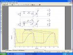
The attached picture shows how a driver (red line) helps. The pulldown resistor on the top diagram is to stop the input floating. Note the timescale on the graph is in uS.

FETs are really simple to wire up - if no driver is used (due to a slow PWM or low currents), you can just connect the gate to the PIC output, and the other two legs as a switch (normally a low side switch).

Andrew
 

Attachments

Last edited:

Dippy

Moderator
AC: "Using logic level FETs is a must with no driver, otherwise the gate voltage will never saturate the capacitor."

- there can still be hefty capacitance values with Logic Level, they simply have a lower threshold. For fast/efficient PWM you will still need a driver.
For slow, simple switching I agree.

A detailed thread from a few weeks ago gave a lot of details.
I wish there were simple examples of popular component use/technical/explanantions in the 'DataSheets' dropdown. Regular contributors must surely get tired of covering the same ground over and over. Though obv it's not over-and-over to newbies. Hence a nice Data Sheet covering general stuff would be nice.
 

Andrew Cowan

Senior Member
Thanks for pointing that out Dippy - I have changed my post. In my thread 'Robot Design', when you told me about using drivers, you said the 4427 was a good driver to use - I found I do not need to order these through Farnell - I have asked for some samples from microchip. Quite possibly A detailed thread from a few weeks ago gave a lot of details. refers to my thread: http://www.picaxeforum.co.uk/showthread.php?t=9568, which has a lot about FETs, drivers, PWM and homemade speed controls in it.

Andrew
 
Last edited:

Andrew Cowan

Senior Member
While it was approaching this, the FET has a small resistance - maybe 1 ohm or so.

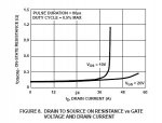
Attached is the graph of for the IRF530 - showing resistance at two different gate voltages.

Although the resistance when it is fully switched on is only 0.14 ohms, a lower gate voltage increases the resistance. You can see this with a FET, a multimeter, and a potential divider connected to the gate.

Andrew
 

Attachments

Dippy

Moderator
This could go round and round. All this sort of info is, as Andrew has shown, in the device Data Sheet.
 

Andrew Cowan

Senior Member
This could go round and round

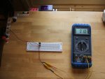
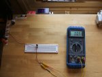
From my tests, an IRF530:
Vgs=3.9 Rds=1
Vgs=11.4 Rds=0.7

Note that these resistances include the resistance of the breadboard, leads, connection, clips etc. The voltage is shown by the blue LED display at the top of the photo.

Current (red display) = needs recalibrating :)

Andrew
 

Attachments

Last edited:
Top