Using Single pin to drive 4 Relays? Possible?

Andrei IRL

Senior Member
Hi everyone and Happy Halloween.
Im working on a project which requires me to cut the spark to 4 ignition coils at the same time.
I would like to use pin PICAXE for this as im trying to make the final assembly as small as possible.
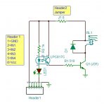
Is it possible to control 4 relays at the same time using single PIN?
The relays i have in mind are 5V coil voltage, they are cheep Chinese relays so i could not get my hands on the data sheet to check how much current coil draws.
I was hoping that if i used a transistor with 800mA output current (BC337 or similar) it might be enough to drive the 4 relays.
Or would i be better off using a larger PICAXE and have a separate pin for each relay?
The operation of the relays will only we for less then a second every time but could be as friquent as 5 operations in 10 seconds at a time.
Thanks very much in advance.
Andrei.
 

westaust55

Moderator
Yes, using a single PICAXE output pin and a transistor will allow you to control multiple relays.
Don't forget to add a diode such as a 1N4001 across each relay coil as a flyback/freewheeling diode to prevent voltage spikes damaging the transistor.

See page 8 in PICAXE manual 3 for the basic circuit:
http://www.picaxe.com/docs/picaxe_manual3.pdf
 

hippy

Ex-Staff (retired)
Not sure what the "spark to 4 ignition coils" would be, but if you are generating any electromagnetic interference in doing that you might have to take some precautions to stop it interfering with PICAXE operation. A 100nF across the PICAXE power pins ( as close as possible to the chip ) would be the minimum.
 

Andrei IRL

Senior Member
Sorry i have another, stupid, question.
I have noticed that there are two different types of the pre assembled Relay shields.
One type is 4-Channel Relay Module Low Level Triger Relay and another type is 4-Channel Relay Module with Optocoupler High Level Triger.
I know that the second type is using optocouplers to operate the coils of the relays but whats the difference between Low level and High level trigger? I know its fairly basic im not 100% on this.
 

Goeytex

Senior Member
With a Low level trigger, a logic "low" will turn on the relay. For confirmation, if you zoom in on the Ebay photo you see the transistors marked 2TY. These are PNP transistors. A PNP transistor needs a "Low" to turn on.

I would get the optocoupler type.
 

Andrei IRL

Senior Member
If i go for the Shield that has optocouplers , will i be able to drive them all as they are or will i have to drive them using a transistor?
 

Goeytex

Senior Member
The required opto current is ~5ma each channel for a total of 20ma. This is marginal for driving directly from a single Picaxe I/O pin. So use a transistor and limit the current with a 220R - 330R Ohm resistor.

Or Put 2 on one I/O pin and 2 on another. Use 330R current limit resistors on the I/O pins.

I wish these cheapo modules had a schematic available. It is "possible" that a current limit resistor is already fitted.
 
Last edited:

Goeytex

Senior Member
The more I look at these cheapo opto relay boards, the more I think they are designed for direct connection to an MCU I/O pin. Many of the opto relay boards on Ebay have both an optocoupler and a transistor for each input. Without a schematic, I cannot tell if the transistor drives the opto emitter AND the LED, or just the LED.

If it were me, as soon as I got one of these thingies, the first thing I would do is ring out all of the connections and create a schematic.

Maybe someone who has some of these can shed more light. Maybe provide a schematic?
 

CDRIVE

Senior Member
The more I look at these cheapo opto relay boards, the more I think they are designed for direct connection to an MCU I/O pin. Many of the opto relay boards on Ebay have both an optocoupler and a transistor for each input. Without a schematic, I cannot tell if the transistor drives the opto emitter AND the LED, or just the LED.

If it were me, as soon as I got one of these thingies, the first thing I would do is ring out all of the connections and create a schematic.

Maybe someone who has some of these can shed more light. Maybe provide a schematic?
No garantee that this is correct because I drew it from the photo found on ebay. So it's a virtual ringout 4 Ch Relay Module
I didn't have the LPC817C Opto (which has 4 pins) so ignore the base pin and the Opto pinout in my schematic. I'm surprised that the opto's LED limiting resistor is 1K especially since they have an indicator LED in series with the Opto's LED.

Edit: I forgot the pdf link to the opto. FOD817

ChrisRelayModuleEbay.JPG
 
Last edited:
Top