Using relays with picaxe chips

Hey guys,
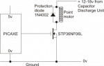
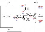
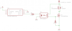
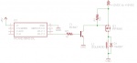
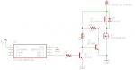
Yet another technical query - this time to do with relays controlled by a picaxe chip. The relays I'm using are the ones listed on the picaxe store, and after doing some reading in the picaxe manuals, it seems I need a transistor driver to power the relays - is this the case?
The picaxe store doesn't have datasheets for the relay, so I don't know what current it draws, whether its above the 20mA source limit for the chip! Will it work connected directly to the chip, without any drivers, as I only need it to be powered for a few ms (10-50 ms) at a time?

many thanks gents
 

inglewoodpete

Senior Member
The TR99-6VDC-SB-CD requires 75mA to operate correctly.

As an aside, relays take time to operate, so even to operate for the shortest time will need some experimenting with driving pulse length.
 

premelec

Senior Member
@danners430 - what's the load you propose to control with the relay?


[My family motto: "Stop & Think - Isn't there a harder way"... ;-0 ]
 

Circuit

Senior Member
It's going to be a Capacitor Discharge Unit - basically, two silly large capacitors working together to deliver a large pulse of electricity to throw solenoids. The relays only need to be active for around 10-20 ms, as the unit has an automatic cut-out. Data sheet here: http://www.gaugemaster.com/instructions/cdu.pdf
You are going to create some pretty whacky sparks at the relay contacts; you would be much better off firing the Gaugemaster unit through a couple of Field Effect Transistors (FETs). You can get MOSFETs that will work well with the PICAXE and the Gaugemaster capacitor discharge unit; I use STP36NF06L - these will switch 30amp continuous and withstand 120amp pulses. They have a relatively low gate threshold voltage (that is the voltage from the PICAXE required to fire them) and, provided you are running your PICAXE at 5 volts then you should have no problem. I have a whole bunch of STP36NF06L switching Fleischmann points through a Gaugemaster CDU and they have been working flawlessly for several years now.
 
That sounds like a convincing argument :) I'll order a few on payday (tomorrow), and fit then when they arrive - right then, where's that manual? :)
 

Buzby

Senior Member
You are going to create some pretty whacky sparks at the relay contacts ...
I thought this too, until I read how a CDU works. An arc happens when a circuit is interrupted, i.e when the switch opens. Using the CDU the current drops very quickly to a few mA, well before the switch is opened, so no arc. It's a simple but clever circuit.

However, I would suggest using MOSFETs instead of relays, they're so Old Skool :)

Cheers,

Buzby
 

premelec

Senior Member
Not sure if you want complete capacitor discharges but if so an SCR might be your easiest route - with due consideration of holding current that will keep it on... on the other hand appropriate MOSFET can work for you - I also haven't read up on just what the beast is...
 
Last edited:
I think I'll go with the MOSFETs, for three reasons - cost (always going to be cheaper than relays and transistors), size and the fact they are solid state - simply more reliable than relays.

I only have one question left, then: if I'm controlling the MOSFET with the Picaxe, which obviously runs off 5V, what do I connect the drain to? I'll have two separate 0V rails - the 5V supply, and the return to the CDU
 

Circuit

Senior Member
I thought this too, until I read how a CDU works. An arc happens when a circuit is interrupted, i.e when the switch opens. Using the CDU the current drops very quickly to a few mA, well before the switch is opened, so no arc. It's a simple but clever circuit.

However, I would suggest using MOSFETs instead of relays, they're so Old Skool :)

Cheers,

Buzby
Well, your theoretical analysis is certainly correct, but believe me, sparks do fly with these things in practice. If the relay operates perfectly and without any contact bounce at all then things would be absolutely as you state. The problem is that only the most stalwart of relays will handle the surge currents properly when the contacts first approximate on activation - especially with a 5 volt coil and at a reasonable cost. Sparks fly, contact plating erodes and sometimes welding of contacts occurs. It takes quite a relay to handle the 120 amp pulse current without suffering any contact damage that the STP36NF06L will handle. The safety margin with the solid state method is way higher than that of a relay at any given price point.
 

hippy

Technical Support
Staff member
I am not sure exactly what role this relay would play in a CDU system but it is worth noting that mechanical relays can take a considerable time to engage and disengage, and also have a far more limited switching cycle lifetime than a solid state solution would have.
 
I am not sure exactly what role this relay would play in a CDU system but it is worth noting that mechanical relays can take a considerable time to engage and disengage, and also have a far more limited switching cycle lifetime than a solid state solution would have.
The CDU is going to be used to switch solenoid point motors, and it outputs a burst of high current, way more than the Picaxe can even imagine handling. The Picaxe controls these solenoids through the relays/MOSFETs.
 

Circuit

Senior Member
I only have one question left, then: if I'm controlling the MOSFET with the Picaxe, which obviously runs off 5V, what do I connect the drain to? I'll have two separate 0V rails - the 5V supply, and the return to the CDU
Perhaps this may guide you:
point motor graphic for website.png

If you have not worked with MOSFETS before, please remember that they are sensitive to static discharge - especially at this time of the year with dry air from central heating combined with woolly-pullies over polyester shirts and rubber-soled trainers/slippers on nylon carpets or whatever. A conductive wrist-strap tied to earth through a 1 Megohm resistor will discharge your body static whilst working. You also need to ensure that there is no static discharge from the work surface that you building your circuit on. Again, a conductive sheet tied to earth via a 1Megohm resistor will do the trick. The casing on your soldering iron may or may not be earthed; if there is a build up of static on your work surface and then you apply the soldering iron to the MOSFET you can get sufficient static discharge of the static build-up through the earthed soldering iron to damage it. Just a few tips for your guidance.
 
OK, I'll connect the 0V rails from both supplies for this. Perfect - and after building PCs, static shouldn't be much of an issue - I work on top of my PC, the case of which is permanently earthed anyway.

Thanks for all your help guys - hopefully I'll have something in the project section soon!
 
Hey again,
So I've discovered a very slight, minor, trivial problem.
Yeah.
The point motors have a common ground output, only the two positive terminals are separate. Is there a way to connect them to the drain of the MOSFET instead?
Many thanks for letting me continue to pester!!!
 

premelec

Senior Member
A schematic would help - are the 'motors' solenoids? Does polarity on the 'motors' matter [on solenoids either polarity should pull ok unless a permanent magnet is involved]. Also there are PMOS as well as NMOS transistors which might work if need be...
 

inglewoodpete

Senior Member
The point motors have a common ground output, only the two positive terminals are separate. Is there a way to connect them to the drain of the MOSFET instead?
You will need to use a "high side" switch (transistor on the positive side of the load). Here is an example of a high-side switch working on a separate, higher voltage supply. This diagram uses a PNP bipolar transistor (Q2) to do the work but you would be better off using a 'P' channel MOSFET. Delete R3, since you do not need to limit gate current to the MOSFET. Connect the gate directly to Q1's collector, source to +ve supply, drain to load+. My choice for P-channel MOSFET is the IRF9540 (VDSS=23Amps / RDS(on)=0.117ohms), because they're easy to get in my part of the world.
HighSideSwitch.jpg
 

rossko57

Senior Member
Almost all 3-wire model point motors will work with either polarity at the common terminal. A confirmation would be if the makers rate them for AC as well as DC, like SEEP do. Some like PECO are 4-wire and you make-your-own common terminal.

I don't know of any with a built in flyback diode, that would cause a polarity problem.

That will allow you to use the more cost effective low-side driver.
 

Circuit

Senior Member
Hey again,
So I've discovered a very slight, minor, trivial problem.
Yeah.
The point motors have a common ground output, only the two positive terminals are separate. Is there a way to connect them to the drain of the MOSFET instead?
Many thanks for letting me continue to pester!!!
Which brand/model of point motors are you using? As the preceding replies indicated, with most solenoids the polarity makes no difference. If it is three wires then chances are that it is a two solenoid job. The BIG exception is the KATO solenoid unit which requires a brief forward/reverse pulse to operate the motor.
 
Hi,
It's the Peco PL-11. I've messaged their support about it... Hopefully they'll get back to me. I think the other Peco motors have separate neutrals...?
 

Circuit

Senior Member
Hi,
It's the Peco PL-11. I've messaged their support about it... Hopefully they'll get back to me. I think the other Peco motors have separate neutrals...?
From the PL-11 instructions http://www.peco-uk.com/imageselector/Files/Instruction sheets/PL-11 Instructions.pdf;

"The Turnout Motor is for low voltage use only. 16v AC at 2 amps is
recommended. The Motor should be energised only momentarily. Never allow
the current to remain on. Use PECO Lever Switch PL-26 or Probe and Studs
PL-17 & PL-18. The motor will work more efficiently with a capacitor discharge
unit (CDU) PL-35, (only one unit per layout needed).​

(Note also that the wiring diagram in the instructions shows no polarity.)

Your answers are right there; the motor works with AC or DC. They recommend 16v AC without a CDU but state that it works better with a CDU - and of course a CDU is a DC device. The polarity, therefore, is irrelevant and you can connect it up with the common to +ve and switch through the negative.

One further word of advice; try various values for PULSOUT to control the points; I found that there is a sweet spot with most motors/point combinations. If you overdo it then you can suffer bouncing or excessive noise. Underdo it and obviously you will get failure of the switch rail to make contact.

Let us know how you get on.
Merry Christmas!
 

premelec

Senior Member
it looks like you could drive the solenoids with 2 NMOSFETS and the solenoid common pin connected through a capacitor with bleeder resistor across it where the + side of the capacitor goes to V+ - this also would prevent inadvertent both sides on problems as the bleeder resistor would be the current limiter... I'm assuming that you don't have to pulse it very often [RxC time constant to bring capacitor down to 0 volts before next charge pulse comes, which charges the capacitor up through the solenoid... ].
 

erco

Senior Member
Barely related: I just got these SIP SPST reed relays off Ebay, whose 512-ohm coils draw under 10 mA at 5V, and they work fine connected directly to 3V. Simple to drive directly from a Picaxe pin (active low best, sink the current), no driver transistor required with the Picaxe powered by 4.5V alkaline cells or a single 3.7V LiPo or Li-Ion. Worth having a couple in your drawer IMO.

http://www.ebay.com/itm/141975921354


AllyCat

Senior Member
Hi,

the solenoid common pin connected through a capacitor with bleeder resistor across it where the + side of the capacitor goes to V+
Yes, I think that is what the Peco CDU basically does. It appears to have a floating (isolated) output (and the solenoid/motor doesn't seem to have any connection to Earth as such). So there should be no problem connecting the "Commoin" wire (which I believe has green insulation) to the "Positive" side. You might consider it as either a "Floating Earth" or a "Positive Earth" system.


Barely related:
Indeed, and sadly that seller doesn't ship to the UK. :(

It seems that the solenoid/motor has a dc resistance of 4.6 ohms, so the current from the expected 20+ volts charged capacitor will be close to 5 Amps. That's near to the maximum contact rating of the original relays (in post #1) but they should be quite satisfactory. However, reed relays are much less tolerant of over-current and inductive arcs, so there would be a severe risk that their contacts might weld together.

To summarise: a pair of Logic Level NMOS FETs with a peak current rating of about 10 Amps seems most appropriate. "Catching" diodes across the coils should be considered essential with any semiconductor switch, but would be wise even when using relays or mechanical switches. NPN power transistors could be "OK" but would need a "Darlington" configuration (or device) to handle the current. SCRs or Thyristors should NOT be used because they're unlikely to switch off with the residual charging current for (re)charging the capacitor.

Don't forget that the "Tabs" of most power transistors (NPN bipolar or NMOS FETs) are connected to their Collector/Drain so should NOT be mounted directly on an Earthed heatsink, nor allowed to touch each other.

Cheers, Alan.
 
Hey guys,
I've received a reply from Peco, and they say that the circuit pictured on page 2 would work fine, and the common neutral can also be used as a positive terminal.
I've ordered some of the MOSFETs which were recommended, so I'll see how I get on with those. Thanks for your help, and merry Christmas!
 

mortifyu

New Member
Hello,

Here are some options...

Option1 - Low side switching:

Option1.png

CPC1981Y is an extremely useful product for isolated low current switching (Up to 180mA).
Using this method will switch the STP36NF06L on fully if using 18V. Even if only using 12V will be ON alot harder than than using 5V as the datasheet shows.
R1 - 10K is necessary to return the FET to the OFF state.
D1 - Merely for protection against back EMF from the solenoid coil.
R2 - Current limiter for the CPC1981Y LED drive.

CPC1981Y Datasheet - http://www.clare.com/home/pdfs.nsf/www/CPC1981.pdf/$file/CPC1981.pdf

STP36NF06L N-Channel Datasheet - http://www.st.com/content/ccc/resource/technical/document/datasheet/ca/9a/86/cf/24/84/4f/34/CD00003405.pdf/files/CD00003405.pdf/jcr:content/translations/en.CD00003405.pdf


Option2 - High side switching:

Option2.png

Simply using a BC547 for control of +12 to +18VDC
R1 - Required to switch the P-Channel FET off when C.2 goes LOW.
R2 - Current limiter for BC547
D1 - Merely for protection against back EMF from the solenoid coil.

IRF9540 P-Channel Datasheet - http://www.vishay.com/docs/91078/91078.pdf


Hope this helps.


Regards,
Morty.
 

mortifyu

New Member
Hello again,

A 3rd Option utilizing the better choice of N-Channel could be...

Option3.png

This circuit requires 2x BC547.

While C.2 is LOW, T1 is OFF allowing T2 to be ON which in turn keeps Q1 from turning ON.

When C.2 is HIGH, T1 is ON stopping T2 from turning ON which in turn allows Q1 to turn ON.

Using the higher rail to switch your FET ON is a much better choice than using 5V if higher currents are required for an output stage. This can be demonstrated by looking at datasheet graphs. Gate to Source Voltage or Vgs.

Why this further variation? Because high current N-Channel FET's are far more abundant and cheaper than high current P-Channel FET's.


Hope this helps.


Regards,
Morty.
 

Circuit

Senior Member
CPC1981Y is an extremely useful product for isolated low current switching (Up to 180mA).
R1 - 10K is necessary to return the FET to the OFF state.
An interesting approach, but you may rest assured that the simple circuit that I showed in post 14 works just fine - firing up a model railway solenoid from a STP36NF06 that is attached directly to a PIC output is a tried and trusted circuit used quite commonly in this application. The 10K is NOT necessary to return the FET to the off state; pulling the PICAXE pin low does that just fine. The only time that it would be necessary to pull the FET gate low would be if there was a danger of something firing in the instant before the PICAXE had booted - not a likely nor critical issue with a model railway point driver - especially as you have to wait a short period whilst the CDU charges.

There is simply no reason to spend money on the CPC1981Y (£2.89 each from Mouser; not listed by RS or Farnell) - it is superfluous to the simple requirements of this application; the STP36NF06 will do 30 amps at 5 volts on the gate. Even just 4 volts on the gate is good for 20 amps - which is dramatically higher than this application will need. There is nothing wrong with your theory (except for the need for the gate pull-down); it is just adding expense and complication to a simple circuit that works very well as is.
 
Last edited:

mortifyu

New Member
There is simply no reason to spend money on the CPC1981Y (£2.89 each from Mouser; not listed by RS or Farnell) - it is superfluous to the simple requirements of this application; the STP36NF06 will do 30 amps at 5 volts on the gate. Even just 4 volts on the gate is good for 20 amps - which is dramatically higher than this application will need. There is nothing wrong with your theory (except for the need for the gate pull-down); it is just adding expense and complication to a simple circuit that works very well as is.
Agreed. It was purely an example of how one could electrically isolate if ever it were required. In the example, the pull down resistor is indeed required, however directly using a PICAXE output to drive the FET one would certainly not require a pull down resistor because as you mention, the PICAXE can do just that with a LOW command.


Regards,
Morty.
 

Circuit

Senior Member
In the example, the pull down resistor is indeed required...
Yes, of course you are correct; I was looking at your text rather than paying proper attention to your schematic - with the intervening devices between the PICAXE and the FET a pull-down is needed.
 
Top