Using Picaxe to close circuit - simple question

Racer_Rob

New Member
Hi,
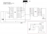
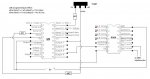
I have a board called a USB 2040 interface, it's a flight-sim thing that gives you two rows of pins and by connecting a push button across 2 pins and closing it it makes the computer think a button such as the trigger on a joystick has been pressed (which can then be set to control some function in the flight sim). Anyway what I want to do is use toggle switches across these pins; problem is when the switch is thrown the computer will see this as 1 continuous button press. So I want to use a picaxe chip so that when the toggle switch is thrown only a pulse of say 0.5sec is sent out, so across the 2pins it just seems like a button press.

I want to do this with 10 toggle switches. My plan is to use 2x 18M chips (with 5 toggles on each chip) as I already have this starter kit I can just replace the current 18M with a new chip and download the programme to it before taking it out to use with the toggles.

Can I do what is shown in the attached picture? (Expertidly done in paint)
Or will I need to use relays? (Please bear in mind im very new it picaxe/ICs)

Manys thanks,
Rob
 

Attachments

chigley

Senior Member
I don't understand the effect of the toggle switches in your circuit diagram. What do they achieve?

To short across two contacts with the use of a PICAXE output, look at the 4066 logic IC. This is a 14 pin IC containing four switches, which are controlled by control pins which you can connect to the PICAXE outputs.

Note that there is a resistance across the in/out pins of the 4066 when the switch is "closed" so make sure that the interface still detects the button press when you short the two contacts with a resistor. The on resistance can be found in the data sheet for your 4066 chip.

If the 4066 isn't suitable, I'd look into relays.

(I'm fairly new here too, some more experienced members may have better advice!)
 
Last edited:

BeanieBots

Moderator
In brief, no you can't.

The simplest and only sure way is to use a relay to replace the contacts.
The next step up would be to use an analogue switch to replace the relay contacts.

To do anything simpler than that will require more knowledge about the circuit you are trying to control. You would also need to identfy the 0v reference of the circuit being controlled.

It might be possible to connect the PICAXE IO direct to the device that requires control but without knowing the device voltages or 0v reference, I'd strongly suggest NOT trying it until you know.
 

Racer_Rob

New Member
chigley, thanks for the reply. I have looked at the data sheet for the 4066 and it has an Res. on of 240ohms so I tested with a 330 resistor and it all still worked ok.

The 4066 looks like a good option, one thing I'm unclear on is what connects to the Vdd and Vss pins of the chips from the data sheet is it the power supply, with +ve on Vdd and Vss on ground?

If this doesn't work out I'll look towards relays as BeanieBots suggested.

(oh and using toggle switches doesn't really 'achieve' anything extra from just a push button, I just got the idea to try it when on the flight-sim and thought it would be a good cheap project to do in the long summer hols)
 

slimplynth

Senior Member
Though it's not exactly the same, take a look at this thread.

http://www.picaxeforum.co.uk/showthread.php?t=12284&page=2

I got the idea to strip a PC keyboard from Australian websites for DIY (refurb) Arcade games. Used 4066 quad bilateral switches, controlled by picaxe to make the PC think a button was pressed. A script (AHK) detected the key press.. then executed commands required to send an email.

I would go with BB's judgement though and exercise caution, nothing worse than killing new toys.
 

BeanieBots

Moderator
For the 4066, Vss is 0v and Vdd is the same supply used for the PICAXE (5v).
Before you hook it up, make sure the 'contacts' to be closed don't exceed your supply voltage or there will be tears.

If they do, there are still ways around it as long as they don't exceed max Vdd for the 4066. (15v).
 

BeanieBots

Moderator
What does the very first sentance of 'his' datasheet say?

20v is ABSOLUTE max. Don't try running it at that.
General rule, for CMOS, 18v max, typical supply = 15v.
Never have any pin > Vdd.
 

Racer_Rob

New Member
Cheers for all the replies, I have done a quick diagram of the circuit for just 1 toggle switch using an 18M picaxe and the 4066 chip. Could someone give it a double check please?

I didn't know what to do with the serial pins as I'll programme it on a tutorial board but it said in the Picaxe manual these still need to have the 22k & 10k res. (plus I didn’t know what the '1,2,3' symbol is?) - I included this in the diagram in the red box.

Edit: from diagram should read
"when input 1 = 1 set output 5 = 1 for 0.5sec
when input 1 = 0 set output 5 = 1 for 0.5sec"
 

Attachments

Last edited:

hippy

Ex-Staff (retired)
You need a pull-down R on Input 1, 4K7 or 10K should be suitable.

If you don't wish to have the board programmable you can connect Serial In to 0V via a 4K7 or 10K ( or even directly to 0V - read past forum posts to save going through the arguments on the merits and otherwise of doing that again ).

You can also leave the Reset switch off and just connect the Reset pin to +V via a 4K7.

It might be advisabe to connect Control A, B and D on the 4066 to either 0V or +V.
 
Last edited:

Racer_Rob

New Member
Thanks hippy, I didn't know that about the reset switch.

Final (hopefully :rolleyes:) diagram is attached with amendments, looking forward to getting started on the build now!

(While it's not the most advanced project out there I'll still post pics when it's done)!
 

Attachments

hippy

Ex-Staff (retired)
Not quite, the 4K7 for Input 1 should be a pull-down to 0V - see Manual 3, Input Switch interfacing.

I said pull-up ealier when I got confused expecting 0V's to be at bottom of circuit, +V at top. It's a good habit to get into, drawing batteries vertically at the side and power rails so +V is at the top and 0V is at the bottom. Saves a lot of confusion and makes a circuit easier to read.
 

Racer_Rob

New Member
ok, I have changed Input 1 and decided to use 10k's instead of 4k7's.

I really see what you mean about drawing the + and - rails at the top and bottom of the page. I never really got why people did that before but after trying to draw a diagram like that it all makes sense :rolleyes:
 

Attachments

hippy

Ex-Staff (retired)
That looks okay now.

You learn many of these things as you proceed, no one is likely to be perfect when they start or know what ( or why ) things are done or what is common convention or 'industry standard'.

On - and + lines, I don't like - lines as this is also a source of confusion. Not so bad in this case where supply is shown between - and + but where -5V and +5V is shown does that mean there's 10V between -5V and +5V ?

The standard is usually 0V and +5V ( or +V, and also Vss for 0V and Vcc for +V, plus a few variations on that theme ), and -5V ( or -V, and so on ) if there's also a negative rail as well. Some people use "ground" to indicate 0V which grates on some people's sensibilities but is usually understandable as synonymous with 0V though not always.

I've seen circuits which use just 0V and -V ( not only automotive, time clocks seem to be the common offenders ) which require a second look to make sure one understands how the circuit works. Something else I'd recommend against.
 
Top