LEDs are also photodiodes plus they have some internal capacitance and it is these two properties that can be used to detect light. I've done this before using AVR & PIC microcontrollers but had never tried it using a PICAXE. I assumed that interpreted basic would be too slow but when I did try it turned out to be tivially easy.
The reference I used is this paper

 www.merl.com
On the PICAXE the commands are:
That's it! You compare the ADC reading you got to a fixed threshold value to determine whether any extra light was being shone on the LED.
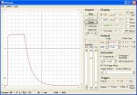
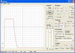
Here are two screen dumps of the signal at the cathode.
The first one is with no extra light shining on the LED and so you see the voltage go to 3V when the cathode pin is set to high. It stays high until we execute the command to make the cathode pin an input, after which the voltage drops in the familiar pattern for discharging a capacitor through a resistor.
The second one is from exactly the same setup but now I am shining a torch into the LED. The photodiode effect provides another path to discharge the LED, which now discharges much quicker.
On an AVR or PIC microcontroller coded in compiled C or assember the idea would be either to time how long it took the pin to discharge down to a particular voltage or to check what level the voltage had dropped to after a fixed time.
For detecting light on a PICAXE I take the second approach, to check what level the voltage has dropped to after a fixed time and this fixed time is simply going to be the PICAXE basic interpreter overhead between setting the cathode pin to an input and taking the ADC measurement. It is a fortunate cooincidence that the time it takes to do a single command on the PICAXE means that the voltage is measured at about the right point early in the discharge of the internal capacitance and we get a big difference in the voltage reading when we shine a light on the LED.
A refinement we can make is to connect the LED between two microcontroller pins. This allows us to use the LED to both detect and generate light. This first program demonstrates the whole process, including this refinement. When you shine a torch on the LED, it turns on.
It does the charge/discharge/ADC measurement and then compares the measured ADC value to a hardcoded threshold. If the measured ADC value is below the threshold it puts the cathode pin low and anode pin high to turn on the LED otherwise it puts both pins low to leave the LED turned off. The ADC values are also sent to serout so that you can see what the values are with no extra light and when extra light is on the LED as an aid to setting the threshold value.
The LED is not giving off any light when the charge/discharge/ADC measurement cycle is being done so you need to set a long enough value for the delay in order for the LED to shine brightly when it is on. As long as the whole loop is more then 100 Hz you should not see any flickering.
The paper TR2003-35.pdf makes these two important points to keep in mind when choosing which LED to use as a sensor:
- The LED is a photodiode that is sensitive to light at and above the wavelength at which it emits. This means that we can expect red LEDs to have a greater sensitivity to white light than yellow, green or blue LEDs.
- LEDs encapsulated in coloured plastic will filter out light that we want to detect. This means that we can expect waterclear LEDs to have a greater sensitivity then LEDs that are encapsulated in coloured plastic.
The reference I used is this paper
Publication - TR2003-35
Mitsubishi Electric Research Laboratories (MERL) - Publication - TR2003-35
On the PICAXE the commands are:
- Set the cathode pin to high. This reverse biases the LED and charges up the internal capacitance
- Change the cathode to an input. This starts discharging the LEDs internal capacitance through the microcontroller pins input resistance.
- Take an ADC reading of the voltage of the cathode.
That's it! You compare the ADC reading you got to a fixed threshold value to determine whether any extra light was being shone on the LED.
Here are two screen dumps of the signal at the cathode.
The first one is with no extra light shining on the LED and so you see the voltage go to 3V when the cathode pin is set to high. It stays high until we execute the command to make the cathode pin an input, after which the voltage drops in the familiar pattern for discharging a capacitor through a resistor.
The second one is from exactly the same setup but now I am shining a torch into the LED. The photodiode effect provides another path to discharge the LED, which now discharges much quicker.
On an AVR or PIC microcontroller coded in compiled C or assember the idea would be either to time how long it took the pin to discharge down to a particular voltage or to check what level the voltage had dropped to after a fixed time.
For detecting light on a PICAXE I take the second approach, to check what level the voltage has dropped to after a fixed time and this fixed time is simply going to be the PICAXE basic interpreter overhead between setting the cathode pin to an input and taking the ADC measurement. It is a fortunate cooincidence that the time it takes to do a single command on the PICAXE means that the voltage is measured at about the right point early in the discharge of the internal capacitance and we get a big difference in the voltage reading when we shine a light on the LED.
A refinement we can make is to connect the LED between two microcontroller pins. This allows us to use the LED to both detect and generate light. This first program demonstrates the whole process, including this refinement. When you shine a torch on the LED, it turns on.
Code:
; LED Sensor - Tuning

setfreq m4

;           08M/08M2
;          .---_---..
;         -|+V   0V|-   D1 - Waterclear Red LED
;         -|C.5 C.0|-  | /|
;         -|C.4 C.1|---|< |--+
;          |       |   | \|  |
;          |       |         |
;         -|C.3 C.2|--/\/\/\-+
;          '-------'    R1 - Current limiting resistor

' Pins
symbol CATHODE = C.1
symbol ANODE   = C.2

' Constants
symbol THRESH  = 130

' Variables
symbol ADC     = b4

main:
    low ANODE            ; Reverse bias LED to charge it up
    high CATHODE

    input CATHODE        ; Then discharge LED through the input pin

    readadc CATHODE, ADC    ; Measure cathode voltage shortly after it starts discharging

    low CATHODE            ; Set cathode low ready to use LED as light emitter

    if ADC > THRESH then    ; If input still above our threshold there was no extra light
        low ANODE        ; so turn the LED off
    else                ; If input now below our threshold there was extra light
        high ANODE        ; so turn the LED on
    endif

    sertxd (#ADC,cr,lf)    ; Trace the ADC reading to sertxd (use to set THRESH)

    pause 50            ; Pause long enough for the LED to appear bright when on

goto mainThe LED is not giving off any light when the charge/discharge/ADC measurement cycle is being done so you need to set a long enough value for the delay in order for the LED to shine brightly when it is on. As long as the whole loop is more then 100 Hz you should not see any flickering.
The paper TR2003-35.pdf makes these two important points to keep in mind when choosing which LED to use as a sensor:
- The LED is a photodiode that is sensitive to light at and above the wavelength at which it emits. This means that we can expect red LEDs to have a greater sensitivity to white light than yellow, green or blue LEDs.
- LEDs encapsulated in coloured plastic will filter out light that we want to detect. This means that we can expect waterclear LEDs to have a greater sensitivity then LEDs that are encapsulated in coloured plastic.
Last edited: