Using 40x1 for the first time - Questions

Basrad

Member
Hi,

First of all a very Happy New Year to all, especially the locals that have helped me out so much last year!

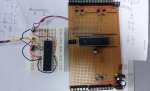
I'm thinking of using a 40x1 to control a robotic arm. No problem with the hardware - its the programming I find tricky.

Last code I used port b or PinB's for the first time. I take it on the 40 it just includes C so you write to PinA. PinB. or PinC.

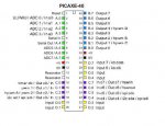
There are 32 I/O .... 9 - 17 x I vs 16 - 23 x O

I've looked at datasheet, Pinout etc, but am not clear on which pins on the chip can be reassigned? All or are some not? Are outputs 0 - 7 (chip pins 33 to 40) reassignable as they are labeled output only on diagram.

Many thanks for any advice
 

eclectic

Moderator
1. Yes, the pins are as labelled on pages 9 and 11 of Manual 1.

2. It might be better to get a 40X2, and then you'll have more definable pins / higher speed .......

e
 
Last edited:

westaust55

Moderator
With the 40X1,
The PortA and PortE pins are permanently configured as inputs. They are primarily used as analogue inputs but can be used as simple digital inputs for high/low tests.
the PortB pins (physical legs 33 to 40) are permanently configured by the firmware as outputs.
The portC pins can be used as inputs or outputs however are restricted to simple high/low functions except where also assigned "special" tasks such as i2c comms
The portD pins are permanently configured as inputs.
 

Basrad

Member
Thanks.

So there are A B C D ports, I have some x1 to use up before getting onto the x2's.

I'm still not 100% sure on which are 'definable pins' Is there a list of definable pins in the manual? I have paper versions, but still havent finnished reading them.

Are ADC's 5 to 7 definable pins? on x1
 

Basrad

Member
With the 40X1,
The PortA and PortE pins are permanently configured as inputs. They are primarily used as analogue inputs but the portA pins can be used as simple digital inputs for high/low tests.
the PortB pins (physical legs 33 to 40) are permanently configured by the firmware as outputs.
The portC pins can be used as inputs or outputs however are restricted to simple high/low functions except where also assigned "special" tasks such as i2c comms
The portD pins are permanently configured as inputs.


:) bingo.. is that a quote from the manual?
 
Last edited by a moderator:

Basrad

Member
Programming problems

Thanks Guys, thats nice and clear..

But now I'm having trouble programming this chip.. I have 4 x 40x1...

Cant seem to communicate with them via the programming USB.. Error - Hardware not found.

Connections as follows:
Pin1 = 4K7 to 5V
Pin6 = 22K to center of jack B with 10K deck after 22K
Pin7 = Straight to outter pin jack A
11 = +5v
12 = 0V
31 = 0V
32 = +5V

Outer pinC of jack to ground..

Should this work? I have missed something?

I dont think I need a crystal for this? Tried both in Circuit and using a programmer vero I've used before modified, but cant get the USB to link with them :(
 

hippy

Ex-Staff (retired)
Pin6 = 22K to center of jack B with 10K deck after 22K
Pin7 = Straight to outter pin jack A
Outer pinC of jack to ground..
It may be worth posting a circuit digram, drawing or photograph of exactly what you have so everyone is clear on exactly how you have it wired.

Not finding hardware can be caused through incorrect wiring of jack socket or having the 10K on the wrong side of the 22K and this could be a case of that.
 

Basrad

Member
Problem found..

Would seem when I was sent these a year ago, they sent the wrong chips.. I have PIC16F877A-I/P instead of 40x1..

Now have 40x1 or x 2 on the way.. thanks for the help
 

nick12ab

Senior Member
What do you mean by "22k to center" and "outer pinC of jack to ground" and a "10k deck"? Hold the jack socket with the pins facing upwards and the jack entry at the top and the pins from left-to-right are serial in, serial in, serial out, ground, ground - the chrome bit is NOT ground, it is serial out. The plug connections are shown in my only blog post - this image:


and the Rev-Ed image:


Next, your 40X1s are supposed to say PIC16F877A-I/P on them - it says so in the chip selection dialog in Programming Editor.
 
Last edited:

Technical

Technical Support
Staff member
Nick - all of your diagrams are wrong - the bottom of the 10k connect to GND, not serial out.
 

westaust55

Moderator
I dont think I need a crystal for this? Tried both in Circuit and using a programmer vero I've used before modified, but cant get the USB to link with them :(
No you do not need a crystal to programme a PICAXE chip.
But you can use a 3-pin resonator or a crystal with 2 capacitors (around 22 to 33 pF) for higher or more stable clock frequencies.

Some of your phrases suggest you may have been trying to program through a PIC (Vellerman ?) programmer.
To do so will erase the firmware that defines a PICAXE chip and render it useless as a PICAXE.
Other comments about 22 and 10 k resistors suggest you may be on the right track.
Schematics as hippy asked you to post could be helpful.
 

Basrad

Member
Thanks, My programming circuit is as it should be...


I have already confirmed I was trying to program a 16F887A without the Picaxe boot thingy. I have received the 40x1's this morning and they work fine... I have a few 16F887A without the picaxe booter, can they be converted into 40x1's?


No - I've only ever used a AXE027 USB lead.. I'm self taught So porbably using phrases incorrectly..

Alls good, going as planned - here is a picture if you like.. I dont normally work to schematics - If it feels right, and it works it does for me.
 

Attachments

westaust55

Moderator
Thanks, My programming circuit is as it should be...

have received the 40x1's this morning and they work fine...
Great to read that you are underway. :)

I have a few 16F887A without the picaxe booter, can they be converted into 40x1's?
Sorry but the answer is NO.
The boot loader (and also BASIC interpreter) is Rev Ed's proprietary software and accordingly they do not release it to the users.
 
Last edited:

inglewoodpete

Senior Member
I have already confirmed I was trying to program a 16F887A without the Picaxe boot thingy. ........ I have a few 16F887A without the picaxe booter, can they be converted into 40x1's?
Um... it's a lot more than a "boot thingy"! There's a whole interpretter and operating system in them there chips. Arduxxxo's have "boot thingys".
 

Basrad

Member
problem Programming.

I'm now getting the error 'cannot find PICAXE-40X1 Compiler.'

'C:\Program Files\ Rev Ed\ Log 4 Pic \ picprog\picaxe40x1.exe'

What can I do to work around this?
 

Basrad

Member
I'm using logicator.. Downloaded from picaxe website yesterday.. (Not at pc to check version)..

Written code in basic view.. Clicked program icon.. Get that error.. Have installed the required MS patches listed already.
 

nick12ab

Senior Member
Logicator should use the 28X1 compiler for the 40X1 since with 40X1 selected I didn't get the error and the text said "PICAXE-28X1 (40X1) enhanced compiler". Try making a copy of the 28X1 compilers in C:\Program Files\Revolution Education\Logicator for PIC micros\picprog or just run the below in the command prompt.
Code:
copy "C:\Program Files\Revolution Education\Logicator for PIC micros\picprog\picaxe28x1*" "C:\Program Files\Revolution Education\Logicator for PIC micros\picprog\picaxe40x1*"
If you're only using the BASIC coding Programming Editor is the recommended software and there's also AXEPAD for Linux and Mac (and Windows) and will run off a pen drive for portability.
 

hippy

Ex-Staff (retired)
I'm using logicator.. Written code in basic view.. Clicked program icon.. Get that error..
That will be something we have to investigate.

It would be better to use Programming Editor to program in Basic rather than writing code in the Basic View and to click on the program icon on the very top toolbar of Logicator rather than the one for Basic View.
 

Basrad

Member
Great, I'll give all these suggestions a go. Has to be Friday now. Will let you know if can fix or work around.
 

hippy

Ex-Staff (retired)
Will let you know if can fix or work around.
This morning you said "I have received the 40x1's this morning and they work fine..." so, if you programmed those then, doing the same again should work just as will as it did previously.
 

Basrad

Member
Hi hippy,

When I said they work fine, what I meant was I was able to check the firmware sucsessfully. (via AXE027)
in both logicator and editor software..


I have just started writing the code this morning, as suggested the Programming Editor has downloaded a test code into the 40x1 with no problem.. Logicator will not download this test code into 40 x 1 for me..

, I want to get my code sorted then I'll play with diffrent programming attmepts.

I am still having diffculty with the code to use for if and outing to these diffrent ports.. How can I upload some code for you guys to have a look at if you would be so kind?


'Robot arm controller BASIC
'14/01/2012


Main: pause 1000

Zeroall: if portA Pin0=1 then ArmIn
high portC 1
pause 250
goto Zeroall

ArmIn: if portB Pin0=1 then GripOpen
high portC 2
pause 250
goto ArmIn

GripOpen: if PortA Pin2=1 then Ready
high portB 7
pause 250
goto GripOpen

Ready: pause 250
high portB 6
pause 250
goto main
 
Last edited:

Basrad

Member
40 x 1 Pinout Diagram

picaxe_40x1 pinout.JPG

I modified this diagram - hope thats okay?!

Think its correct, colours seem to help me work.. I'm having trouble with the syntax for my code now.

if PortA.1 OR if PortA Pin1 OR if PinA.1 ??
and then its different for High / Low commands?
 

hippy

Ex-Staff (retired)
I'm having trouble with the syntax for my code now.

if PortA.1 OR if PortA Pin1 OR if PinA.1 ??
and then its different for High / Low commands?
IF commands use just pinX for reading the default input pins ( on port D ) and HIGH / LOW commands use just X for default output pins ( on Port B ).

Port A are the default analogue inputs but can also be used as digital inputs in IF commands by using PORTA pinX.

Port C are additional I/O so can also be used as digital inputs in IF commands by using PORTC pinX or as digital outputs by using PORTC X.

So these are the command options available on the 40X1 ...

Code:
If       pinX = 1 Then ' Reads D.X
If PortA pinX = 1 Then ' Reads A.X
If PortC pinX = 1 Then ' Reads C.X

High       X           ' Sets B.X
High PortB X           ' Sets B.X
High PortC X           ' Sets C.X
So, you cannot read port B as input or use port A nor port D as output.
 

westaust55

Moderator
View attachment 10099

I modified this diagram - hope thats okay?!

Think its correct, colours seem to help me work.. I'm having trouble with the syntax for my code now.
Since you are using a 40X1 chip you would do better as a reference to use the 40X1 pinout diagram from PICXAE manual 1(currently V7.7) page 9.

Note that:
1. the pin addressing scheme for the X1 parts does not use the port.pin method as used for X2 asnd M2 parts, there are 16 pins assigned as digital IO where the pin is permanently an input or an output.
2. the Serial OUt pin (physical pin 7) cannot be used as a part of Port A in any way.
 

Basrad

Member
Since you are using a 40X1 chip you would do better as a reference to use the 40X1 pinout diagram from PICXAE manual 1(currently V7.7) page 9.
.
This diagram does not show all the information I require.. Where is port B, D, .... For someone new to these chips, and a very basic understanding to guess which pin is which,

For example if i want D.4 or D.5 they are not indicated on page 9.

Serial OUt pin (physical pin 7) cannot be used as a part of Port A in any way.
Thanks, Ill update my pic -

Hopfully going to make some progress now.

Thanks for the example codes Hippy!
 

Basrad

Member
Please have a look at Manual 1, pages 40 - 41.

It should give you a better idea.

e
The 40x1 diagram doesnt.. but the 40x2 gives me the information I need for the 40x1.

As recommended by eclectic. Page 96 book 1 gives the most comprehensive info relating to 40x1, but there is no diagram.. hence my modifiyed diagram combining 40x1 diagram and the information on page 96 together.
 

hippy

Ex-Staff (retired)
This diagram does not show all the information I require.. Where is port B, D, .... For someone new to these chips, and a very basic understanding to guess which pin is which,

For example if i want D.4 or D.5 they are not indicated on page 9.
That was really my fault for bringing new port.pin notation into it when that doesn't apply to the older 40X1. On the 40X1 there are no port B and port D pins as such, only standard input pins and standard out pins, then port A and port C pins.

What are standard input pins on the 40X1 are port D on the 40X2 and standard output pins on the 40X1 are port B on the 40X2. On the 40X1 the input pins can only be inputs, the output pins only outputs, port A can be analogue or digital inputs, port C can be digital inputs or outputs.
 
Top