Using 08M as PWM driver

Basrad

Member
Good day, Im trying to setup a 08M to use as a PWM driver with 8 states of output...

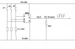
As far as i can see, only Pin 5 or Output Pin 2 can be setup as the PWM out?

I want to use 3 Input pins to trigger the 8 states....

3 Bit... 000 = OFF upto 111 = fastest Frequency

All seems to be working fine, except for Input pin 1 (Pin 6)

When the chip is powered up and all I/P are tied down to 0, Its in its off stage.. COOL

But when I/P 1 is bought high then low, the Output latches ON, and wont go off..

Reset the chip, and bring the other I/P's 3 and 4 High or Low, and every thing works fine...

Any ideas why I/P 1 or Pin 6 on the 08M chip wont play ball???
 

Basrad

Member
Do you need code? Afraid im only working in flow so far...

When I operate Switches 2 & 3 the circuit does as expected.. But on switching S1, the output latches high, and will not switch off again...

Help Please :)
 

Attachments

Last edited:

techElder

Well-known member
For one thing, your schematic doesn't show that you have the standard serial input circuitry, 10K & 22K, on LEG 2 SERIAL IN.

SERIAL IN needs to see ground and not remain floating.
 

Basrad

Member
Ok, The 10K was there, and the other R is part of a program lead I clip on...

Double checked these, and the problem remains the same :(
 

MartinM57

Moderator
That doesn't sound right in the long term - the 22K should be immediately connected to the SERIAL IN pin - it shouldn't be part of a programming lead that you can connect/disconnect. It sounds like you have a 22K/10K potential divider feeding into the SERIAL IN which is incorrect - you might get away with it but it's wrong.

So the question is, are you successfully programming the chip - try a test program that wiggles an output pin very second just to make sure.

So a FULL schematic and a photo would still help ;)

Also, not many here use flowcharting as a means of programming - why don't you have a go at a PICAXE BASIC version - it's not too hard...
 

Technical

Technical Support
Staff member
From the flowchart menu click 'Convert to BASIC' and then you can post your BASIC.
 

eclectic

Moderator
I've just built the circuit,
using an 08M on an AXE091 board.

Code:
#picaxe 08M


do
let b1 = pins
sertxd (#b1,cr,lf)

loop
does indeed show strange behaviour on Pin1.
Why? Well Pin2 (PWMout) upsets the numbers.

This works
Code:
#picaxe 08M

dirs = %00000100

do
let b1 = pins
sertxd (#b1,cr,lf)

loop
e

Addit See Manual 2, p. 129
 
Last edited:

hippy

Ex-Staff (retired)
One trick for handling 'pins' and avoiding those not used or outputs is to take the individual pin bits and form a number from them, such as ...

b0 = pin4 * 2 | pin3 * 2 | pin1

Remember that PICAXE maths is left to right so the first *2 is correct, it isn't *4 !

That will give a number 0 to 7 in b0, %000 to %111, which can then be used in a SELECT CASE or LOOKUP ( and sometimes also READ ) to get values to use for PWMOUT etc.
 

Basrad

Member
So doing this is making b0 = what is read on Pin 1 & Pin 3 & Pin 4

Then is b0 = to

That looks and sounds simple for a flow chat beginer like me!,
Iv never done any code before, Will have to look, Cant quiet work out how this is done using the flow chart version,

But many thanks for all the ideas!
 

Technical

Technical Support
Staff member
You are correct, in flowchart mode use
Other > Let > b0 = pins & 26
(26 in decimal is the same as %00011010)
 
Top