Useful started project! Perhaps...

cactusface

Senior Member
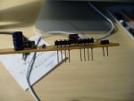
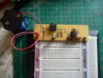
I have to confess that the original idea for this was not mine, my mate Peter Taylor who has had many years experience playing with electronics, but only a little with the picaxe. Peter came up with this idea for a small PCB that would carry an 08 Picaxe with power and the download circuits, also included were header contacts (Sockets really) to allow easy connection to a breadboard via wire links, even the power headers (fitted upside down) plugged in to the breadboard power rails, and thus power the board too.

I initially copied this but my BB (=Breadboard) had the power rails at the top and bottom, not on the sides as his, so I had to modify my PCB making it a bit longer. With the extra space, could I also fit a 20pin socket in there? But then I noticed that the top 4 pins of the 08 Picaxe and 20 were the same. So just by fitting a 20pin socket you could program both sizes, then the next day I discovered that the 14pin devices also fit with the same top 4 pins providing the power and Sin and Sout on identical pins.

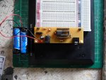
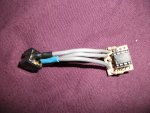
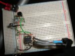
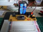
The other mod I made to Peter's circuit was to add a 2 pin header for battery connection and flip the socket strips so all 8 pins/contacts also plugged directly into the BB! But on the 20 pin version I thought that all 20 pins making contact directly onto the BB was just a bit over-kill. I have all the Diptrace schematic and PCB files, if anyone want's to try it.

Nice useful project for a starter perhaps?
Hope it's useful.
Regards
Mel.

08DL-2.JPG0820DL-2.JPG
 

srnet

Senior Member
Can you connect the battery to the two pin header the wrong way around, if so what happens to the PIC ?
 

cactusface

Senior Member
Useful Starter project perhaps..

Can you connect the battery to the two pin header the wrong way around, if so what happens to the PIC ?
Smet,
Yes of course you can connect the battery the wrong way around! but why would you want to?? in other words it's not that hard to watch what you're doing. Perhaps a diode would'ent go a miss, or a legend on the board like +.
Russbow Yes I've seen your boards before, in fact I commented on them and the weather station also shown, by the way how did you get your wind speed data??

Being able to program and run 3 different Picaxes on one little PCB is not too bad, and quite useful. ;)
Anyway here's another couple of pictures.

Regards
Mel.

08DL-1.JPG0820DL-1.JPG
 

booski

Senior Member
This is my own version of the 08M programmer I made to be able to be inserted into the breadboard and programmed.
It's a little nasty but it works a treat and leaves space either side of the chip to add wire links for testing.

DSCF0533.JPGDSCF0534.JPG
 

srnet

Senior Member
Yes of course you can connect the battery the wrong way around! but why would you want to??
You would not want to of course, as you stand a fair chance of destroying the PICAXE and any other devices connected to the + and -.

I admire your confidence that you wont ever make a mistake, but you will, one day.
 

booski

Senior Member
Smet,
Yes of course you can connect the battery the wrong way around! but why would you want to?? in other words it's not that hard to watch what you're doing. Perhaps a diode would'ent go a miss, or a legend on the board like +.
Russbow Yes I've seen your boards before, in fact I commented on them and the weather station also shown, by the way how did you get your wind speed data??

Being able to program and run 3 different Picaxes on one little PCB is not too bad, and quite useful. ;)
Anyway here's another couple of pictures.

Regards
Mel.

View attachment 9380View attachment 9381

I'm curious as to why you have wire links on both the ground lines as the ground lines travel along the entire width of the board, whereas the power lines separate in the middle hence wire links would be needed to join them :)
 

Goeytex

Senior Member
Nice Project Mel,

My current (main) breadboard supports 3 Picaxes simultaneously via three CP2102 USB Modules each having its own extension cable & Com Port. A 74HC14 does the serial inverting for all three. A fourth Picaxe can be added in a moment using the PC Serial Port and standard serial cable The board is USB powered instead of using a battery pack. But it's an easy switch to a battery pack. The USB to serial Modules needed to be programed with unique serial numbers in order to enumerate correctly and have different serial ports ( Com 4, 5, 6). I use multiple instances of Hercules Serial ( Freeware) so that three terminals can run simultaneously for debugging via sertxd.
 

cactusface

Senior Member
Hi Srnet,
Sorry I really did'ent mean so sound like a smartie pants!! I'm far from it, and you know what they say about the chap who never made a mistake? I've made plenty but made some useful stuff along the way.
Booski Love your tiny 08m board or plug in module. I'm curious as to why the wire links fascinate you so much, but in the 20pin version I have managed to get rid of them all, and this I am currently using.
Goeytex Your board sounds quite something, but must be quite a size? Just a couple of things, the original 08m board fitted on the right hand side of the BB but the 20pin version fits on the left hand side, as this suits my cable arrangements better.

Most of this as come about after I discovered the Laser printer method of producing PCB's it's by far the simplest way to produce PCB artwork. I use Diptrace to create the schematic then convert it to a PCB file. I even used to use a program for laying out Veroboard, but it's a waste of time you can produce a proper PCB by then, but that's another story.
Regards
Mel.
 
Last edited:

rbright

Member
CactusFace Quote "I have all the Diptrace schematic and PCB files, if anyone want's to try it. "
Can you publish the schematic & PCB please

Thanks
 

cactusface

Senior Member
Useful starter project! Perhaps

Hi Rbright.
Here's the files for the 08-20 version which I hope is the one you want. It should be obvious which is which, don't forget to rename them using the right EXT. Please take a look and tell me what you think? I have modded both to include a protection diode, if using 4 rechargeable AA's I usually get about 5V depending on load, so take your pick! as to type. Should anyone else like a try be my guest.

My breadboard came from Maplins for under a £5, I already had one so now it's two fixed down together.

Regards
Mel.

View attachment 081420-DownLoader-SCHEMATIC.DSN View attachment 08M-20MDownLoaderDiodeZZ-PCB.DSN
 
Last edited:

westaust55

Moderator
Concur that it would be good to have the schematics etc published now.
That will avoid others at a future date having to search around to see if yet posted or contact you in weeks/months/years to come.


Ron Hackett in his book "PICAXE Microcontroller Projects for the Evil Genius"
also has one of the first project to build a power supply module to providing regulated power to both sides of a BreadBoard.

Chapter 3 Designing and Building a +5V Regulated Power Supply
Designing a +5V Regulated Power Supply for Breadboard Circuits

Photos in the book and on Rons website: http://www.jrhackett.net/

Book available through Rev Ed on-line store: http://www.picaxe.com/Getting-Started/Where-Next/
 

cactusface

Senior Member
Useful Starter project perhaps..

Hi Westy,
Thanks! I think it could be useful too. Just another thought for those of you who don't use Diptrace or would like to convert the circuit to Vero-board, etc. The 2 PDF files below give you the schmatic and PCB in plain English (Sorry all you folks in the US and Oz). Please note that in the schematic the Picaxe 20? is just there to represent an empty 20 pin DIL socket and can be an 8,14 or 20 pin device. With current devices pins 1 & 2 must fit sockets 1 & 2 also.

Happy programming.
Regards
Mel.

View attachment 08-20DownLoader.pdf View attachment 081420-DownLoader.pdf
 
Top