USB communication and power

evans_us

Member
Hi all
I have always used a USB serial converter to commnicate with my circuits. However, many of the circuits I have been using lately are very small - using the 08M (and moving to 08M2 very soon :)). The problem is that the power supply (even a wall wart) and serial (DB9) converter make the required package very large. My question is whether anyone has a circuit that can use USB communication through to the picaxe and can also supply the 5V needed for the circuit? If so do you need a USB driver for communication and do you need a special command to access this from VB.net?
Many thanks for any answers
Cheers
Evans_us
 

aduy

Senior Member
what you can do is get a cheap prolific usb to serial cable, then take it apart and extract the pcb out of it. remove the db9 jack, and hard wire it to the picaxe, then attach any usb type b port that you have or like to the usb end of the pcb, and your done. thats as small as it gets for usb, unless you design the chip that converts usb to serial into your design.
 

Goeytex

Senior Member
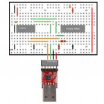
This is what I use. Never had a problem. To save board space the inverter(s) can be 2 SOT-23 transistors.
instead of the 74HC14.

You can program the EEprom on these for a unique serial number. You can also program
a "power byte" into the EEprom that tells the USB bus how much power(milliampss) to allocate
for the device. This is for a direct 5v via the USB bus. The 3.3v output is from an on board regulator
and is good to 100ma. I would derate to 60 or 70ma max.

These adapters are available on Ebay for < 5.00 and use a genuine CP2102 USB to Serial Bridge IC.

I would stay away from the Prolific based adapters unless you are prepared to spend some time hunting drivers
, dealing with poor quality soldering and/or fake (generic) PL2303 chips.
 

Attachments

Last edited:

Jamster

Senior Member
As USB is 3.3V you will need to step up the voltage to 5V
OR
When you get the 08M2, if the rest of the circuit will work at 3.3V, you can power it directly from USB.

The PICAXE will not work with USB coms directly, however if you buy the AXE027 (which you could disassemble and rebuild to supply power) you will be able to comunicate as you would the DB9 connector as there is a driver which acts as a virtual serial port.

Jamster
 

nick12ab

Senior Member
Code:
  O
\/|\/
(here to lengthen post)
I'm not completely sure what the stick figure is doing, but my guess is that it's meant to mean that you don't know what I'm on about. Is that correct and I need to explain a bit better or does it mean something else? Alternatively it could be a flower with big leaves.
 

Goeytex

Senior Member
Let's get specific.

USB Vbus is 5v. (power bus)
The data signal is about 3.2
Get your scopes out an measure it. I did.

I think I read here where one of the Rev Ed guys ( Hippy maybe ? ) said that the output of the AXE 027 is 3.3v. Since the Axe027 interfaces reliably with Picaxe Processors powered at 5v, it would stand to reason that the logic high input threshold voltage of the Picaxe I/Os is pretty low. The PIC datasheet for the 18F14K22 ( 20x2) shows 2.0 volts (min)with 5v Vdd. My testing has shown it to be reliable to 1.6v given a 5v supply on a 20x2. (This can vary from pin to pin and chip to chip.)

Logic level translation ( step up) should not be necessary from a USB to Serial Bridge IC (3.3v data) to a Picaxe running at 5v. In other words 3.3v is good enough to be seen as a "high" by a Picaxe operating at 5v.

Goey
 
Last edited:

Technical

Technical Support
Staff member
I think I read here where one of the Rev Ed guys ( Hippy maybe ? ) said that the output of the AXE 027 is 3.3v.
Nope, AXE027 is a 5V logic device powered by the 5V USB port. However it can safely program both 5V and 3V PICAXE systems via the standard download circuit.
 

Jamster

Senior Member
I'm not completely sure what the stick figure is doing, but my guess is that it's meant to mean that you don't know what I'm on about. Is that correct and I need to explain a bit better or does it mean something else? Alternatively it could be a flower with big leaves.
No i understood, it was meant to mean a sort of i don't know/probably, although it obviously didn't.

It could be a flower though...:)

EDIT: I think i was thinking about the data signals.
 

evans_us

Member
USb circuit

I really liked the solution Goeytex posted. I found the adpaters on Ebay for $4 (S/H inlcuded from HK). I will fiddle with other things while I wait for the 4 weeks for the slow boat from China to deliver my parts. I think I can get the package size down to a very reasonable size with this solution.
Thanks for all the answers.
Will post on results when I have some.
Cheers
Evansus
 

Goeytex

Senior Member
@evans_us

The CP2102 will come with its EEPROM "power byte" set to 100ma, meaning that the operating system will read this byte and allocate 100ma from the USB Vbus to the CP2102 board. Try to use much more than that on a steady basis and there will be problems. (Error message, etc ,) This is true for any USB device with the power byte set.

If you need more than 100ma you can program the CP2102 EEPROM with the ID Utility from Silabs. I wouldn't go past about 150. This can be read by opening Device manager and looking at USB Controllers > USB Root HUB . Select the HUB that the CP2012 is attached to. > Power.
 

renatose

New Member
Alternately you could use Silabs driver tools/utilities to modify the driver to make
RX and TX signals to/from the CP2102 "active high". This will eliminate the need for hardware inversion.
Can you please give me exact instructions on how to do this?
I also have the CP2102 bought on ebay as a TTL/RS232 to USB adapter.
 

mrburnette

Senior Member
...
My question is whether anyone has a circuit that can use USB communication through to the picaxe and can also supply the 5V needed for the circuit? If so do you need a USB driver for communication and do you need a special command to access this from VB.net?
Many thanks for any answers
Cheers
Evans_us

I use http://shop.moderndevice.com/products/bub_ii but get them from www.phanderson.com already reprogramed for inversion... Peter also has the Windows driver link. To my knowledge, with WinXP the driver must be loaded but I do not know if Win7 has a "generic" driver that will load.

- Ray
 
Last edited:

renatose

New Member
The link posted above is for FTDI only & is not applicable to your CP2102.

Correction: The CP2102 cannot be programed to be active high. Only the FDTI Chip has this capability. Therefore hardware inversion will be necessary with the CP2102.

One of these should work very well and not take much space.

http://www.semicon.panasonic.co.jp/ds4/DMC20101_CED.pdf
http://www.nxp.com/documents/data_sheet/PMP4501V_G_Y.pdf
thank you, I've already ordered a 74HC14 it should also do the job.
 
Top