URF/ERF modules

keith j

Member
Hi All,

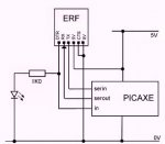
I have looked at the wiring diagrams supplied with these items and although I can identify some of the places I need to wire the erf to I cannot identify others. Does anyone know if there is an idiots guide to wiring the erf to a AXE020 board (am using a 28 X 1 PICAXE chip), or have any other helpful tips on this subject.

Many thanks

Keith
 

hippy

Ex-Staff (retired)
Basically take the ERF "TX" signal to a digital input (SERIN) and take a digital output pin (SEROUT) to ERF "RX". The ERF "DTR" signal can be left unconnected, or optionally connected to an LED and/or a PICAXE digital input ....
 

Attachments

keith j

Member
Hi Hippy,

Many thanks that makes it a lot clearer - I shall try it. I thought I had to solder the erf to the same connections on the board that the cable uses, not that I can use the digital pins on the board to do the same job.

Do I have to programme the PIC before I can use the erf of will the erf's on board chip have the necessary software (I have already downloaded the software file from picaxe)

Keith
 

hippy

Ex-Staff (retired)
For wirelessly programming, the ERF connections go to the Download Circuit Serial In and Out pins, as described on page 5 of the datasheet -

www.picaxe.com/docs/RFA020.pdf

The best way of connecting is probably using flying leads from AXE020 board, from pins on the 28-pin socket.

You do not have to program the PICAXE to use wireless programming.
 
Top