Universal PICAXE Programmer Board

MearCat

Member
I have been playing with various PICAXE chips for a few years now and have usually been programming them while in place on-board, or using a home-built programmer (on an experimenters board using multiple ZIF sockets).

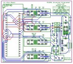
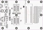
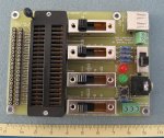
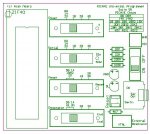
It's been bugging me for a while that I couldn't find an all-in-one board that would suit everything from 8 pin through to 40 pin PICAXE, so over the weekend, I designed this (see attachment for PCB overlay). It measures 80mm x 70mm and has a single 40-pin ZIF socket to fit any 5V PICAXE chip.

There are 4x four-throw slide switches to select the chip used. Each switch is for a "function" (Power, Serial Communication, Reset, Resonator). I was initially going to use a rotary switch but they are too bulky and didn't think there would be too much of a problem having multiple switches as long as they're laid out neatly.

Other items :
- Terminal block to screw in any external resonator
- Tactile pushbutton for reset
- Standard 3.5mm stereo plug for the AXE027 cable
- LED for indicating circuit power
- LED which is lit during program download

I did create another design which was the same as this one but above all these components, had a 9V battery PCB clip on board with a 78L05 and decoupling caps, but that was before I remembered the current rating of the PP3 9V batteries are quite low and wasn't sure how long a 9V battery would last in this application.

I haven't yet fabricated the board (or tested of course), but I thought I'd get feedback first to see if I could improve it. Comments?
 

Attachments

Last edited:

westaust55

Moderator
For constructive comments about your own board, you should post a schematic diagram for folks to review.
A PCB layout does not convey a lot of information.
 

MearCat

Member
How the heck did I miss the AXE091 :confused: In saying that, I still would have balked at that price and did design my board for programming only and not as a Dev board.

Here's the track/PCB layout but I don't have a schematic on me right now. I'll post that later. Each switch electrically isolates the "Function" to the appropriate ZIF pins.
 

Attachments

Last edited:

kollinsb

Member
Did you have a look at the rev Ed produced AXE091 Progammer Board ? :confused:
http://www.rev-ed.co.uk/docs/axe091.pdf

Available (at a cost) from MicroZED on the east coast of Aust: http://www.microzed.com.au/index.php?main_page=product_info&cPath=28&products_id=141
I must say that the AXE091 board is well worth the money, every penny. I use mine all the time. A ZIF socket would be nice on the board but there would need to be 3 of them and that would raise the price of the board a lot so, not worth it.

**thinking**

I may add a ZIF or two to mine.:cool:
 

BCJKiwi

Senior Member
Hmm, designed a board for this ages ago but as I did not have board making facilities and the cheap sources were not so readily available, it was shelved - maybe time to resurrect it?

Contains the programming circuit, power supply, a single 40 pin ZIP, Sip sockets for every pin, and, resonators.

Utilises a movable plug to select Picaxe type.

So allows for programming and connection to external circuits for development.

see attached pic of layout

Any interest?
 

Attachments

Last edited:

MearCat

Member
It's interesting to see how different trains of thought can produce different solutions to the same design requirement - for a universal board. I wasn't intending to sell my design en-mass, but it does raise the question - Would there be any issues (With eg. Rev-Ed) in someone designing a programming board like mine (or BJCKiwi) and selling it?
 
Last edited:

inglewoodpete

Senior Member
It's hardly fair to compare MearCat's basic programming board with the AXE091 development board. They are each targetted at different jobs.

I prefer to do in-circuit development so always include the download socket and 2 resistors on my boards. Less chance of damaging a PICAXE chip (physical and ESD). But that's my personal choice.
 

tarzan

Senior Member

Technical

Technical Support
Staff member
You are basically re-inventing a variation on a product we discontinued several years ago as we simply did not sell enought to make it a viable product! We simply found most people used the PICAXE as intended and recommended, via including the download socket on each and every project board. If you want to make your own feel free, but we do not think it is a commecial product for us to stock.


http://www.rev-ed.co.uk/docs/axe080.pdf

 
Last edited:

MearCat

Member
You are basically re-inventing a variation on a product we discontinued several years ago as we simply did not sell enought to make it a viable product! .... If you want to make your own feel free, but we do not think it is a commecial product for us to stock.
Thanks for the approval ;) I did actually say in a previous post that I wasn't intending to sell my design en-mass. This was designed with personal use in mind ... but if anyone is interested, I guess I could get a small run made and sell them once it's all tested etc

I have a question in regards to the the discontinued AXE080, what approx average battery life would you expect get with the 9V battery in it?
 

srnet

Senior Member
I have a prototype board which I use for both PICs and PICAXEs.

Its fitted with 3 40pin ZIF sockets, they cost me £2 each delivered.
 

Technical

Technical Support
Staff member
I have a question in regards to the the discontinued AXE080, what approx average battery life would you expect get with the 9V battery in it?
For the battery shelf life if only switched on and off for the 20second programming period!

The 78L05 regulator, and in your case, LEDs, take far more juice than just the PICAXE itself.
 

MearCat

Member
@MearCat, Some feedback as you originally requested. I can't see a 0v connection to the programming socket.
Cheers - I spotted that this afternoon. I forgot to reconnect the track when I moved the connector. I've messed up the download circuit in general.
 
Last edited:

Texy

Senior Member
It's hardly fair to compare MearCat's basic programming board with the AXE091 development board. They are each targetted at different jobs.

I prefer to do in-circuit development so always include the download socket and 2 resistors on my boards. Less chance of damaging a PICAXE chip (physical and ESD). But that's my personal choice.
Same here - I,m always tinkering with the code anyway, so it makes sense to add the d/l socket, etc - the parts are so cheap, its silly not too.

Texy
 
Nice idea

Here's the track/PCB layout but I don't have a schematic on me right now. I'll post that later. Each switch electrically isolates the "Function" to the appropriate ZIF pins.
I like your idea, do you have a part number and manufacturer name for those switches?
 

BCJKiwi

Senior Member
Yes - interesting differences in approach.

Where mearcat's board is programmer only, the route I chose was to provide a programmer with the external connections so it could be used while developing the circuit on an attached breadboard - thus a programmer and development board in one covering all chip sizes in a single unit.

Also, to avoid the issues with switches, I chose to use a relocatable plug - while maybe not as elegant as switches it means there is only a single item to move eliminating the risk of not getting the combination right.

Should be simple to extend to provide both 3V and 5V supply options.

Quite happy to make the circuit available.
I like your concept. Please publish the schematic.
Thank you for sharing
 

westaust55

Moderator
I like your idea, do you have a part number and manufacturer name for those switches?
Suspect they were purchased from Altronics.
Have a look at www.altronics.com.au
Select switches at the left side of home page and then select slide switches to go to that section for a Cat No. 2 pole 4 position slide switches are there.

EDIT:
Now at a larger screen and looking on the Altronics webset here is the page:
http://www.altronics.com.au/index.asp?area=item&id=S2040

As you are in the US, you might email Altronics for more details to enable purchase locally - or "bite the bullet" and purchase from Australia - we don't bite, but the AUD$ might :D

EDIT2:
another possible source (Element14 are worldwide):
http://au.element14.com/te-connectivity-alcoswitch/sts2400pc04/switch-slide-dp4t-300ma-125v-thd/dp/1291137?Ntt=Slide+Switch+DP4T
 
Last edited:

Ambutech

New Member
If you get this all working, I will buy 2 or 3 PCBs. I have mates at work and at the radio control model boat club, who might be interested too.

Rgds
 

BCJKiwi

Senior Member
TTDesign AXEPROG Schematic and Board

@ Marmitas

Attached is both the schematic and the board in Diptrace. Rename AXEProgS.dsn to AXEProgS.dch and AXEProgB.dsn to AXEProgB.dip

The schematic was done long before the board. The board has been reworked since and the tracks optimised by hand. The checking was all done on the PCB Layout as mousing over a trace lights it up throughout its connected length which I found the easiest way to verify that the connections went to the right places for each selected option.

The large number of mounting holes are to ensure full support of the board during handling and insertion of selector plug/resonator(s)/flyleads to bread board etc.

On reflection I would just make more than one board to handle the 5V/3V issue - I figure I would probably make say 4 of these to handle the different voltages and multi-picaxe circuits.

The selector is simply a flat ribbon cable plug jumpered through with flat ribbon cable.

I have hand made a prototype using a modified KPic board but it is a programmer only (which I find inconvenient for development) - see following post for Pic.

If anyone makes some boards would appreciate a few coming my way;)
 

Attachments

Last edited:

BCJKiwi

Senior Member
The pic of KPIC board prototype.

The socket in the bottom right corner is not connected to the circuit - somewhere to keep the plug.
 

Attachments

Last edited:

cactusface

Senior Member
PicAxe programers..

Hi Mearcat and BCJ,
A multi PicAxe programmer, now that's what I want! Mearcat looks like a nice job, do you have the schematic or PCB files it Diptrace format?? I could make my own PCB.

I'll subscribe to this thread and wait to see what happens! :)
Regards
Mel.
 

MearCat

Member
I have just received the 2x prototype boards done of my Universal Programmer. It took ~10 minutes to solder it together and I've tested serial communications with the PICAXE Programming Editor with a 08M, 18, 28X1 and 40X1 chip and they all communicate successfully. I will test all other connections/pinouts another day ... soon.

Two items I've added to the original design is a USB cable connection to power the board and two pin headers for connection to eg. an external breadboard (although powering the board with the USB cable will have limited current for external connections). Total board dimensions are 95mm x 70mm.

Note that I did not get a soldermask for the prototype.

Update : I have now tested the remainder of the board and had a small batch fabricated and will sell them (with soldermask this time) so just PM or email me and let me know if you are interested in purchasing one.
 

Attachments

Last edited:
Top