Uln2003 output
- Thread starter CLUELESS1
- Start date
westaust55
Moderator
The ULn2003 and ULN2803 are low side switches with one side of each channel tied to ground.
The UDN2981 is a high side switch with one side of each channel tied to the supply line.
If one side of the load is tied to ground then the UDN2981 is the solution albeit often more expensive than the ULN2x03 chips.
How many relays are you trying to control? If just one this can be easily down with 1 (for low side) or at most 2 (for high side) transistors.
Many thanks. I made a mistake on a board layout. The relays (5) are for remote control, so only one at a time on. I connected relays to ground (0v on relay) and each positive of relays to 5 outputs of ULN2003. I kept making the Picaxe outputs switch high/low and could not get the output of the ULN to switch, then finding the device won't switch to ground. I thought the ULN2803 would be okay, as looked the other way round. Is it no good?, went and ordered one. Regards
I haven't heard of the UDN2981 before, but a quick a quick look at both datasheets shows pins 9 and 10 are reversed between the UDN and the ULN, so some "chopping the board around" will still be required.
Just found this previous post
Just found this previous post
No worries. At first glance, they are indeed a drop-in change-over from one to the other  .
.
Your location mentions OXFORD, I'm guessing you are not 30km away from me, but in UK? An even bigger guess would be that I would have heard your screams from HERE!!
I suspect it may be easier to modify your existing board. Cut the copper GND trace that connects all the relays together from the rest of the board. Then solder a wire to supply and the common relay trace.
Good luck.
.Your location mentions OXFORD, I'm guessing you are not 30km away from me, but in UK? An even bigger guess would be that I would have heard your screams from HERE!!
Technically, the ULN is switching to ground, as the output pins are Open Collector. Therefore they need a load (relay coil in this case) to be tied to a voltage rail, and the other end of the coil is being switched to GND via the ULN. Make sense?I kept making the Picaxe outputs switch high/low and could not get the output of the ULN to switch, then finding the device won't switch to ground.
I suspect it may be easier to modify your existing board. Cut the copper GND trace that connects all the relays together from the rest of the board. Then solder a wire to supply and the common relay trace.
Good luck.
Thanks again, yes I am in the UK.
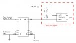
I am trying to use the UDN2981 to feed one side of a relay, with the other side of the relay connected to ground.
The attached shows what I am trying to do, but from a Picaxe, and the opposite end going to ground and not +5 volts (circuit shows 12v, but I am using 5v)
I am trying to use the UDN2981 to feed one side of a relay, with the other side of the relay connected to ground.
The attached shows what I am trying to do, but from a Picaxe, and the opposite end going to ground and not +5 volts (circuit shows 12v, but I am using 5v)
Can you point us to a UDN2981 datyasheet... the Allegro one I saw is an 18 pin.
And you appear to have +12V(5V) to pin 9 and the other side of relay coil also to +12V(5V). Eh?
Is this your own drawing of just lifted from some random site?
And I assume your 5V relays will switch OK at 5V - Vce = ~3.5V ish ?
And you appear to have +12V(5V) to pin 9 and the other side of relay coil also to +12V(5V). Eh?
Is this your own drawing of just lifted from some random site?
And I assume your 5V relays will switch OK at 5V - Vce = ~3.5V ish ?
Oh heck you are right, it's an 18 pin. I began my search for an opposite to the ULN2003, and somehow sidetracked off course. Will retrace my steps, and start again. Regards and thanks, not my day
EDIT. Found where I went wrong, I followed a Google thread where someone was asking if there was an inverted version of the ULN2003 or ULN2803. The answers back all referred to inverted 2803's which I did not notice. Now I cannot find a version for the 2003. Is there one?
EDIT. Found where I went wrong, I followed a Google thread where someone was asking if there was an inverted version of the ULN2003 or ULN2803. The answers back all referred to inverted 2803's which I did not notice. Now I cannot find a version for the 2003. Is there one?
Last edited:
westaust55
Moderator
http://www.ti.com/lit/ds/slis019a/slis019a.pdf
I have not used these suggest you make sure you can locate a seller before you design to suit the chip.
edit:
Forget the above chip (TPIC2701) as it is a common source not source driving :-(
Seems (from my searching) there is no 7 channel version available as the compliment of the ULN2003.
If there is a moral to be had ==> test (breadboard) before committing to a final PCB.
Last edited: