two SerOut commands

Jaden

Senior Member
Hi,

I need to send two register values out my RF chip to a Rx. I can do it with one command but having trouble receiving the second. The question. Should I use this,
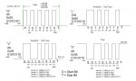
Code:
b20=pinsA AND %0111111                 'look at specific pins
SerOut A.4, N2400,(b20)
pause 50
b21=pinsB AND %11110000
SerOut A.4, N2400,(b21)
At the Rx end
Code:
serin C.3,N2400,(b20)
pause50
serin C.3,N2400,(b21)
or can I go something like
Code:
b20=pinsA AND %0111111                 'look at specific pins
b21=pinsB AND %11110000
SerOut A.4, N2400,(b20, b21)
pause 50

am using a 40x2 to a 14M2.
Thanks
 

westaust55

Moderator
The use of a single SEROUT with multiple byte variable values is possible.

What is the specific problem you are experiencing?
Are the two PICAXE chips operating at their default clock speeds (8 MHz for the X2 and 4 MHz for the M2)?
(good to post the complete programs or at least a respectable portion of each so folks have a better idea where your problems might be)

What Tx and Rx modules are you using?
Rev Ed or other? Do they include encoding.
If they are cheap basic AKS types including a preamble and qualifier may be a good idea.

Can you run the M2 at 8 Mhz and use the N2400_8 parameter to see if that resolves the problem you are experiencing.
 

Jaden

Senior Member
OK, both chips are running at default frequencies.
When I run debug on the 14M2 I cannot see the BCD values (0 to 9) coming through. The 14M2 receives the serin command and forwards highs to a 20M2, the 20M2 drives two separate seven segment set-ups and I do not want the 20M2 pausing while waiting for a serin command so the 14M2 is a go-between!

Code:
Symbol siren_led = D.1
Symbol resetsc_led = D.0
Symbol pausesc_led = C.2
Symbol startsc_led = C.1
Symbol resetgc_led = C.0
Symbol startgc_led = A.7
Symbol signal_out = A.4
'
Symbol startgc = A.0
Symbol resetgc = A.1
Symbol startsc = A.2
Symbol pausesc = A.3
Symbol resetsc = A.5
Symbol siren = A.6

'Symbol bcdA = B.7
'Symbol bcdB = B.6
'Symbol bcdC = B.5
'Symbol bcdD = B.4

symbol x = b0


'------------------------------ LED TEST -----------------------------------------

High siren_led						'turn siren Led on
pause 300							'wait 0.3 seconds
Low siren_led						'turn Srien Led off

High startgc_led						'turn Strat GC Led on
pause 300							'wait 0.3 seconds
Low startgc_led						'turn Start GC Led off

High startsc_led						'turn Reset GC Led on
pause 300							'wait 0.3 seconds
Low Startsc_led						'turn Reset GC Led off

High pausesc_led						'turn Start SC Led on
pause 300							'wait 0.3 seconds
Low pausesc_led						'turn Start SC Led off

High resetsc_led						'turn Pause/Reset SC Led on
pause 300							'wait 0.3 seconds
Low resetsc_led						'turn Pause/Reset SC Led off

High resetgc_led						'turn Reset SC Led on
pause 300							'wait 0.3 seconds
Low resetgc_led

'again

for b0 = 1 to 3 step 1
High siren_led						'turn siren Led on
High startgc_led						'turn Strat GC Led on
High startsc_led						'turn Reset GC Led on
High pausesc_led						'turn Start SC Led on
High resetsc_led						'turn Pause/Reset SC Led on
High resetgc_led						'turn Reset SC Led on

pause 300							'wait 0.3 seconds
Low siren_led						'turn Srien Led off							
Low startgc_led						'turn Start GC Led off
Low Startsc_led						'turn Reset GC Led off							
Low pausesc_led						'turn Start SC Led off
Low resetsc_led						'turn Pause/Reset SC Led off
Low resetgc_led
pause 300
next b0
						
						
pullup on 			; enable pullups on 28X2-5V
	pullup %11110000


'------------------------------ Main -----------------------------------------

main:

' 0 - 11110000
' 1 - 01110000
' 2 - 10110000
' 3 - 00110000
' 4 - 11010000
' 5 - 01010000
' 6 - 10010000
' 7 - 00010000
' 8 - 11100000
' 9 - 01000000
									' 
	b21= pinsB AND %11110000				'Read value on BCD switch on pins pinsB 4,5,6,7
	SerOut A.4, N2400, (b21)				'send b19 value out pin A.4


	b20 = pinsA AND %01101111				'look at pinsA, 0,1,2,3,5,6
	SerOut A.4, N2400, (b20)				'send b20 value out pin A.4
	pause 50								

	'debug
	goto main							'keep looking at this value
At the Rx end
Code:
 ' PICAXE-214M2
 ' Serinhandle.bas
 ' Picaxe handles the SERIN comand and sends highs out to 20M2
 '
 
Symbol siren = C.0						'pin 7
Symbol resetsc = C.4						'pin 3
Symbol pausesc = C.2						'pin 5
Symbol startsc = C.1						'pin 6
Symbol resetgc = B.1						'pin 12
Symbol startgc = B.2						'pin 11
Symbol status = b20						'
Symbol bcdcount = b21


' Registers used
' b20, b21, b22
' b20 - Which button is pressed
' b21 - What is the value of the BCD switch


main:

	'serin c.3,N2400, bcdcount				'look at incoming from control panel, assign value to 'bcdcount value' (b21)

	serin C.3,N2400, status					'look at incoming from control panel, assign value to 'status' (b20)
	
	if status = %01000000 then high siren 		'look to see if siren button pressed
	endif
	if status = %00100000 then high resetsc		'look to see if reset SC button pressed
	endif
	if status = %00001000 then high pausesc 		'look to see if pause/resume SC button pressed
	endif
	if status = %00000100 then high startsc 		'look to see if start SC button pressed
	endif
	if status = %00000010 then high resetgc 		'look to see if reset game clock/all button pressed
	endif
	if status = %00000001 then high startgc 		'look to see if start game clock button pressed
	endif
	pause 75

	
	let pinsC = %00000000					'reset pinsC to low
	let pinsB = %00000000					'reset pinsB to low
	
	
	goto main
 

westaust55

Moderator
Going back to your first post, sugegst that remove the PAUSE 50 between the two SERIN commands.
The X2 can be given a pause duration which can be helpful but for the M2 part, it needs after receiving the first byte to
1. save the byte value into the variable
2. wait for 50 ms
3. set up the next SERIN command
4. receive the second byte.

So removing the 50 ms pause between SERIN commands will give the M2 part time to handle the first byte and get ready for the second byte.

Again, I ask the question what Tx and Rx modules are you using?
 

Jaden

Senior Member
Thanks, I always have this notion that the Picaxe is going to fast for itself! I did read a good article PICAXE RF Connect Kit (AXE213), available from all good picaxe sites, that showed this as well.

Sorry I did not read about the Tx & Rx chips, my bad..... I have it working with one serin command already, http://embedded-lab.com/uploads/datasheets/Rx_KST-RX806.pdf. They due use ASK for the modulation so should I use
Can you run the M2 at 8 Mhz and use the N2400_8 parameter to see if that resolves the problem you are experiencing.
.

Thanks
 

westaust55

Moderator
It is not essential that both chips run at the same speed.
From a quick look at that Datasheet have you included a preamble and a brief pause before sending the actual data to "precondition" the Rx end?

This has been mentions in many past threads.
So add before the SerOut to the Tx module

Serout A.4, N2400, ("UUUUUU")
Pause 10

You may also want to:
1. Add a qualifier (see the PICAXE manual under Serout)
2. Try getting it working initially at a slower baud rate and on e working properly the. Increase the baud rate to 2400
 

lbenson

Senior Member
And make sure that it works when the modules are wired together before you try it wireless--that can simplify a very difficult debugging process.
 

hippy

Ex-Staff (retired)
Thanks, my next question was for someone to explain 'preamble' for me.
Preamble is what is sent to condition the receiver ready for reception of data.

It's akin to the familiar 'bing-bong' at the start of a supermarket public address announcement. The 'bing-bong' gets attention, there's a pause to let everyone get ready to listen, a qualifier to indicate who the announcement is directed at, and then the message itself.
 

Jaden

Senior Member
OK Folks a bit further down the track again...
I have now stripped it back to the bare minmum and I am running a hard wire between my Tx (40x2) board and my Rx board and still canmot get it working. I am also getting a little further with the help of the VSM software. My Rx controlling Picaxe does not seem to be getting past my serin command, in the debug mode (Programming editor) the Tx board is sending what it is supposed to, my Rx board does not seem to be passing it on. The VSM simulator shows only C.4 of the Rx chip as on (blue not grey). Below is my Tx and Rx program.

Tx
Code:
' Picaxe 40x2
' It all starts here
' Control Box
' Build #1


Symbol siren_led = D.1
Symbol resetsc_led = D.0
Symbol pausesc_led = C.2
Symbol startsc_led = C.1
Symbol resetgc_led = C.0
Symbol startgc_led = A.7
Symbol signal_out = A.4
'
Symbol startgc = A.0
Symbol resetgc = A.1
Symbol startsc = A.2
Symbol pausesc = A.3
Symbol resetsc = A.5
Symbol siren = A.6

symbol x = b0
symbol y = b1


'------------------------------ LED TEST -----------------------------------------

High siren_led						'turn siren Led on
pause 300							'wait 0.3 seconds
Low siren_led						'turn Srien Led off

High startgc_led						'turn Strat GC Led on
pause 300							'wait 0.3 seconds
Low startgc_led						'turn Start GC Led off

High startsc_led						'turn Reset GC Led on
pause 300							'wait 0.3 seconds
Low Startsc_led						'turn Reset GC Led off

High pausesc_led						'turn Start SC Led on
pause 300							'wait 0.3 seconds
Low pausesc_led						'turn Start SC Led off

High resetsc_led						'turn Pause/Reset SC Led on
pause 300							'wait 0.3 seconds
Low resetsc_led						'turn Pause/Reset SC Led off

High resetgc_led						'turn Reset SC Led on
pause 300							'wait 0.3 seconds
Low resetgc_led

'again

'flash all LED's 3 times

for b0 = 1 to 3 step 1
High siren_led						'turn siren Led on
High startgc_led						'turn Strat GC Led on
High startsc_led						'turn Reset GC Led on
High pausesc_led						'turn Start SC Led on
High resetsc_led						'turn Pause/Reset SC Led on
High resetgc_led						'turn Reset SC Led on

pause 300							'wait 0.3 seconds
Low siren_led						'turn Srien Led off							
Low startgc_led						'turn Start GC Led off
Low Startsc_led						'turn Reset GC Led off							
Low pausesc_led						'turn Start SC Led off
Low resetsc_led						'turn Pause/Reset SC Led off
Low resetgc_led
pause 300
next b0
						
						
pullup on 			; enable pullups on 28X2-5V
	'pullup %11110000


'------------------------------ Main -----------------------------------------


'BCD switch values
' 0 - 11110000
' 1 - 01110000
' 2 - 10110000
' 3 - 00110000
' 4 - 11010000
' 5 - 01010000
' 6 - 10010000
' 7 - 00010000
' 8 - 11100000
' 9 - 01000000

main:


'
' http://www.picaxeforum.co.uk/showthr...ustralia/page4 for more explination on preamble
'
'SerOut pin 21/D.2
									' 
	
	b20 = pinsA AND %01101111                                           'watch the button input pins for change of state on all except pins 
	
	SEROUT D.2, N2400_8, ($55, $55, $55, $55, $55)	              'wake up the Tx & Rx chip  'Preamble to wake Rx chip up

	pause 10                                                                          ' short wait
	serout D.2,N2400_8,(b20)  				'send b20 value out pin D.2
		
	gosub buttonpr
	'debug
	goto main							'keep sending the button press state value
	
	
'---------------------------- Panel Display -----------------------------------	
	
buttonpr:
	
	'for x = 1 to 3 step 1
	
	do while pinA.0 = 1					'if startgc is pressed then 
		high startgc_led					'light LED
	loop								'loop while pressed
	low startgc_led						'low LED when released and next
		
	do while pinA.1 = 1
		high resetgc_led
	loop
	low resetgc_led
	
	do while pinA.2 = 1
		high startsc_led
	loop
	low startsc_led 
	
	do while pinA.3 = 1
		high pausesc_led
	loop
	low pausesc_led
	
	do while pinA.5 = 1
		high resetsc_led
	loop
	low resetsc_led
	
	do while pinA.6 = 1
		high siren_led
	loop
	low siren_led
	
	'next x
	return
	end
Rx
Code:
 ' PICAXE-14M2
 ' Serinhandle.bas
 ' Picaxe handles the SERIN comand and sends highs out to 20M2
 '
 
Symbol siren = C.0						'pin 7
Symbol resetsc = C.4						'pin 3
Symbol pausesc = C.2						'pin 5
'Symbol startsc = C.1						'pin 6
Symbol resetgc = B.1						'pin 12
Symbol startgc = B.2						'pin 11
'Symbol status = b20						'
'Symbol bcdcount = b21


' Registers used
' b20, b21
' b20 - Which button is pressed
' b21 - What is the value of the BCD switch


main:

'pin 4/C.3 pin10/B.3
	
	
	serin 4,N2400_8,b20					'look at incoming from control panel, assign value to 'bcdcount value' (b21)
	pause 10
	let b20 = %00000010
	
	'debug	
	if b20 = %01000000 then high C.0 			'look to see if siren button pressed
	endif	
	if b20 = %00100000 then high C.4			'look to see if reset SC button pressed
	endif
	if b20 = %00001000 then high C.2 			'look to see if pause/resume SC button pressed
	endif
	if b20 = %00000100 then high C.1 			'look to see if start SC button pressed
	endif
	if b20 = %00000010 then high B.1 			'look to see if reset game clock/all button pressed
	endif
	if b20 = %00000001 then high B.2 			'look to see if start game clock button pressed
	endif


	let pinsC = %00000000					'reset pinsC to low
	let pinsB = %00000000					'reset pinsB to low


	goto main
 

lbenson

Senior Member
>I am running a hard wire

I hope you are running two--you have to have a ground between the two circuits.

You really need a qualifier as well so that the receiver (when wireless) can pick out the data byte (and when wired, so the serin ignores the conditioning $55s).

serout D.2,N2400_8,("ABC",b20)

...

serin 4,N2400_8,("ABC"),b20

Use anything you want instead of "ABC".
 

Jaden

Senior Member
Yep had the earth, I have added

Code:
serout D.2,N2400_8,("11111111",b20)
Code:
serin 4,N2400_8,("11111111"),b20
Now on the Tx board when I run the debug mode I get bits sending out for b20 & B22 (b21 is remmed not to send out). But at the Rx end same thing, the debug mode will not run, just keeps waiting, I believe this is why the outputs that are supposed to show on the simulator are greyed out, because it is not getting past the serin command.

Thanks
 

Jaden

Senior Member
mmmm. Ok trying a few sugestions but still not getting anywhere. AS shown below when I put a value into b20 I get a result, if I run the debug mode without this forced value and when it asks for the same value it will give a high on the chosen output with that value! So again, the serin is missing something?

Code:
' PICAXE-14M2
 ' Serinhandle.bas
 ' Picaxe handles the SERIN comand and sends highs out to 20M2
 '
 #picaxe 14m2
 
'ymbol siren = C.0						'pin 7
'ymbol resetsc = C.4						'pin 3
'ymbol pausesc = C.2						'pin 5
'Symbol startsc = C.1						'pin 6
'ymbol resetgc = B.1						'pin 12 
'ymbol startgc = B.2						'pin 11
'Symbol status = b20						'
'Symbol bcdcount = b21


' Registers used
' b20, b21
' b20 - Which button is pressed
' b21 - What is the value of the BCD switch


main:

'pin 4/C.3 pin10/B.3
	 
	serin C.3,N2400_8,b20  
	
	let b20 =%00000100

',("11111111")
		
	select case b20
		case %01000000
			high c.0					'if b20 = value then high C.0
		case %00100000
			high C.4					'if b20 = value then high C.4
		case %00001000
			high C.2					'if b20 = value then high C.2
		case %00000100
			high C.1					'if b20 = value then high C.1
		case %00000010
			high B.1					'if b20 = value then high B.1
		case %00000001
			high B.2					'if b20 = value then high B.2
			
				
	endselect


	debug
	
	let pinsC = %00000000					'reset pinsC to low
	let pinsB = %00000000					'reset pinsB to low


	goto main
	en
 

hippy

Ex-Staff (retired)
I have now stripped it back to the bare minmum ...
You haven't, not really. There is far too much going on in the program making it hard to spot the mistakes in your code. The I/O pins used keep changing and you do not seem to be fully taking on board what people are suggesting. Try this -

Code:
#Picaxe 40x2
Do
  SerOut D.2, N2400, ( "XYZ", b20 )
  Pause 1000
Loop
Code:
#Picaxe 14M2
Do
  SerIn C.3, N2400, ( "XYZ" ), b20
  Toggle C.0
Loop
This will simply toggle the 14M2 C.0 output every time a byte of data is sent to it, once a second. Once that is working you can build up from there.
 

Jaden

Senior Member
Yes it is starting to get confusing (for me). The circuit will toggle the output C.0, so it says that the SerIn IS getting data from the Tx board, and further to that it is not what is being sent seeing that it is not satisfying one of the below conditions? Running debug mode on the 40x2 I can see the correct 8 bits being sent and also changing state at the Tx end when they are supposed to . Like you said I could be way of the beaten track. I have looked at the serin/serout parts of the manual many times and still not sure what I am doing wrong. Thanks for your persistence so far.

Code:
	Do 
	  SerIn C.3,N2400,("11111111"),b20               'Tx end sends the qualifier '11111111' to wake the Rx up before taking b20 value.
	  
	select case b20
		case %01000000
			high C.0					'if b20 = value then high C.0
		case %00100000
			high C.4					'if b20 = value then high C.4
		case %00001000
			high C.2					'if b20 = value then high C.2
		case %00000100
			high C.1					'if b20 = value then high C.1
		case %00000010
			high B.1					'if b20 = value then high B.1
		case %00000001
			high B.2					'if b20 = value then high B.2
			
		
	endselect
	'debug
	let pinsC = %00000000					'reset pinsC to low
	let pinsB = %00000000					'reset pinsB to low


	Loop
 

hippy

Ex-Staff (retired)
Yes it is starting to get confusing (for me). The circuit will toggle the output C.0, so it says that the SerIn IS getting data from the Tx board, and further to that it is not what is being sent seeing that it is not satisfying one of the below conditions?
It's probably getting confusing for everyone. When you say it toggles the C.0; with what code ? That suggested in post #17 or something else ?

How do you know it is not receiving the correct data ? Again, using what code, particularly what is the sending code ?

Don't go rushing ahead in great leaps and bounds because there are a number of reasons things may not be working, including clearing the outputs immediately after setting them. If the code in #17 works the next step is as follows -

Code:
#Picaxe 40x2
Do
  SerOut D.2, N2400, ( "XYZ", b20 )
  Pause 1000
  b20 = b20 + 1
Loop
Code:
#Picaxe 14M2
#Terminal 4800
Do
  SerIn C.3, N2400, ( "XYZ" ), b20
  SerTxd( #b20, " " )
Loop
 

Jaden

Senior Member
Don't go rushing ahead in great leaps and bounds because there are a number of reasons things may not be working, including clearing the outputs immediately after setting them.
On the ball there hippy, I need to stop trying to get to much going first, the frustrating bit was that half way through this post I could Tx and Rx the 8 bits no problems! So I have done something to stuff it up along the way..... Anyways. Now (with your bits in) C.1 output on the 14M2 will toggle high. I was thinking that somehow I was receiving the wrong data for b20? So if I am understanding it correctly you are incrementing b20 each time to toggle consecutive outputs to high at the Rx end?

This is what I am sending (below), basically at this stage the Tx board looks at 6 switches and send their state to the Rx board.

Hope this helps some.

Code:
' Picaxe 40x2
' It all starts here
' Control Box
' Build #1
#Picaxe 40x2

Symbol siren_led = D.1
Symbol resetsc_led = D.0
Symbol pausesc_led = C.2
Symbol startsc_led = C.1
Symbol resetgc_led = C.0
Symbol startgc_led = A.7


Symbol startgc = A.0
Symbol resetgc = A.1
Symbol startsc = A.2
Symbol pausesc = A.3
Symbol resetsc = A.5
Symbol siren = A.6

'Symbol bcdA = B.7
'Symbol bcdB = B.6
'Symbol bcdC = B.5
'Symbol bcdD = B.4

symbol x = b0
symbol y = b1


'------------------------------ LED TEST -----------------------------------------

High siren_led						'turn siren Led on
pause 300							'wait 0.3 seconds
Low siren_led						'turn Srien Led off

High startgc_led						'turn Strat GC Led on
pause 300							'wait 0.3 seconds
Low startgc_led						'turn Start GC Led off

High startsc_led						'turn Reset GC Led on
pause 300							'wait 0.3 seconds
Low Startsc_led						'turn Reset GC Led off

High pausesc_led						'turn Start SC Led on
pause 300							'wait 0.3 seconds
Low pausesc_led						'turn Start SC Led off

High resetsc_led						'turn Pause/Reset SC Led on
pause 300							'wait 0.3 seconds
Low resetsc_led						'turn Pause/Reset SC Led off

High resetgc_led						'turn Reset SC Led on
pause 300							'wait 0.3 seconds
Low resetgc_led

'again

'flash all LED's 3 times

for b0 = 1 to 3 step 1
High siren_led						'turn siren Led on
High startgc_led						'turn Strat GC Led on
High startsc_led						'turn Reset GC Led on
High pausesc_led						'turn Start SC Led on
High resetsc_led						'turn Pause/Reset SC Led on
High resetgc_led						'turn Reset SC Led on

pause 300							'wait 0.3 seconds
Low siren_led						'turn Srien Led off							
Low startgc_led						'turn Start GC Led off
Low Startsc_led						'turn Reset GC Led off							
Low pausesc_led						'turn Start SC Led off
Low resetsc_led						'turn Pause/Reset SC Led off
Low resetgc_led
pause 300
next b0
						
						
pullup on 			; enable pullups on 28X2-5V
	'pullup %11110000


'------------------------------ Main -----------------------------------------


' 0 - 11110000
' 1 - 01110000
' 2 - 10110000
' 3 - 00110000
' 4 - 11010000
' 5 - 01010000
' 6 - 10010000
' 7 - 00010000
' 8 - 11100000
' 9 - 01000000

main:

'SerOut pin 21/D.2
									' 
	
	b20 = pinsA AND %01101111
	b21 = pinsB AND %11110000				'Read value on BCD switch on pins pinsB 4,5,6,7


	Do
	    serout D.2,N2400,("XYZ",b20)  			'send b20 value out pin D.2
	    Pause 1000						
	    b20 = b20 + 1


	'gosub buttonpr
	debug
	Loop							'keep looking at this value
	
	
'---------------------------- Panel Display -----------------------------------	
	
buttonpr:
	
	'for x = 1 to 3 step 1
	
	do while pinA.0 = 1					'if startgc is pressed then 
		high startgc_led					'light LED
	loop								'loop while pressed
	low startgc_led						'low LED when released and next
		
	do while pinA.1 = 1
		high resetgc_led
	loop
	low resetgc_led
	
	do while pinA.2 = 1
		high startsc_led
	loop
	low startsc_led 
	
	do while pinA.3 = 1
		high pausesc_led
	loop
	low pausesc_led
	
	do while pinA.5 = 1
		high resetsc_led
	loop
	low resetsc_led
	
	do while pinA.6 = 1
		high siren_led
	loop
	low siren_led
	
	'next x
	return
	end
 

lbenson

Senior Member
Hippy's code is not related to what you are trying to do in your receiving program except for the part about making sure that you are receiving what is sent.

Is that working now?

When it is, you can move on to seeing if it works wirelessly, and then on to making your sender send what you want it to, and your receiver do what you want when it gets what is sent.

Please put your code postings within [ code ] and [ /code ] (without the spaces) so that the indentations and spacings which we hope you are using for readability can be seen. You can go back and edit your prior post to do this.
 

Jaden

Senior Member
Yeah I had the start code tag but did not close it! but corrected it as soon as I posted, you were to quick for me lbenson. I can see that hippy's code is testing that the serout/serin function is happening, I am still using it on the VSM software as it is a lot easier to visually see what is happening this way. I am also plugging it into my actual circuit.
 

Jaden

Senior Member
Sorry also omit the C.1 toggling high, I forgot to take that out as per hippy's last bit of code. No o/p's are going high, only the serial input pin C.3.
 

Jaden

Senior Member
Ok a bit of success..

I can do the below and get the correct 8 bits out the other end as it starts of my two digit countdown. That is it send a high to C.i on the Rx board.

Code:
	Do
	b20 = pinsA AND %01101111
	b21 = pinsB AND %11110000				'Read value on BCD switch on pins pinsB 4,5,6,7


	let b20 = %00000100
	    serout D.2,N2400,("XYZ",b20)  			'send b20 value out pin D.2
	    Pause 1000						
	    b20 = b20 + 1


	'gosub buttonpr
	debug
	Loop
Code:
	#Terminal 4800
		Do 
	  SerIn C.3,N2400,("XYZ"),b20  
	  	SerTxd( #b20, " " )
I remove the ("XYZ") when I am in the simulation mode so the program runs to the end.
 
Last edited:

Jaden

Senior Member
Ok folks I know I am getting to be a pain but believe me I do appreciate your help. But this is screwing with my mind!

From the code above I have narrowed my problem down the the Rx end. When I run the program in the simulation mode in the Programming Editor and it asks me for the Serin data and I put in say 00000100 which in turn sends C.1 high, but it skips right past it! . If I put b20 = %00000100 in the program it will work. I will be trying the actual hardware at work tomorrow but I would have thought that it should work in the simulator. As far as I can read the serin command is correct?

Thanks again.

Code:
 ' PICAXE-14M2
 ' Serinhandle.bas
 ' Picaxe handles the SERIN comand and sends highs out to 20M2
 '
 '#picaxe 14m2
'Symbol siren = C.0						'pin 7
'Symbol resetsc = C.4						'pin 3
'Symbol pausesc = C.2						'pin 5
'Symbol startsc = C.1						'pin 6 
'Symbol resetgc = B.1						'pin 12 
'Symbol startgc = B.2						'pin 11
'Symbol status = b20						'
'Symbol bcdcount = b21
' Registers used
' b20, b21
' b20 - Which button is pressed
' b21 - What is the value of the BCD switch
main:
'pin 4/C.3 pin10/B.3 
	serin 4,N4800,("XYZ"),b20
	pause 10
        select case b20
		case %01000000
			high C.0					'if b20 = value then high C.0
		case %00100000
			high C.4					'if b20 = value then high C.4
		case %00001000
			high C.2					'if b20 = value then high C.2
		case %00000100
			high C.1					'if b20 = value then high C.1
		case %00000010
			high B.1					'if b20 = value then high B.1
		case %00000001
			high B.2					'if b20 = value then high B.2
	endselect
	'endif
       'debug
	let pinsC = %00000000					'reset pinsC to low
	'let pinsB = %00000000					'reset pinsB to low
	goto main
Note: I remove the ("XYZ") when in simulation mode so the program can run through with only putting the serin string.
 
Last edited:

nick12ab

Senior Member
Ok folks I know I am getting to be a pain but believe me I do appreciate your help. But this is screwing with my mind!

From the code above I have narrowed my problem down the the Rx end. When I run the program in the simulation mode in the Programming Editor and it asks me for the Serin data and I put in say 00000100 which in turn sends C.1 high, but it skips right past it! . If I put b20 = %00000100 in the program it will work. I will be trying the actual hardware at work tomorrow but I would have thought that it should work in the simulator. As far as I can read the serin command is correct?
How does it know that 00000100 is supposed to be in binary? Try entering the number in decimal (4).
 

lbenson

Senior Member
"4" is still going to be ASCII. I don't know that it will work, but try <control>-d, which may give you a binary 4.
 

nick12ab

Senior Member
"4" is still going to be ASCII. I don't know that it will work, but try <control>-d, which may give you a binary 4.
Not in simulation mode unless the quotation marks are used - I didn't specify use quotation marks. However this is true for the terminal built into PICAXE Programming Editor.
 

Jaden

Senior Member
WoW nick12ab! It works. Putting 4 in the Simulation widows when it asks for a serial data works! Now I am confused....

My understanding and please correct me on what I am doing.

I have 6 buttons, I looked at them in debug mode and got 6 8 bit strings to represent each button press. I then put whatever button press is into b20 and send it to the Rx chip, which I thought read the 00000100 at the other end?

Hippy I must say .....Ahhhh! I see what you are saying and I did not know I could do that :). Thanks.

I seem to be thinking wrong that it will send a value, eg, 00000010 and receive the value 00000010? SP at the Rx end even though I am sending a binary number I should represent it at the Rx end by its ASCII value?

This has helped me to sleep a little better at night! But I still love the little picaxe.
 

Jaden

Senior Member
Well after looking at the debug mode and talking to a Motarola pic programmer I see the error in my ways, and like bit bangging it has opend my eyes to the way picaxes do things.....Is it actually sending Hex?? This will help me get closer to the finish line.
Put the char value into the serial data box and all is good in the simulator.

Thanksso far all.
 
Last edited:

westaust55

Moderator
@Jaden,


Motarola pic programmer
Hint: The PIC chips are manufactured by Microchip upon which the PICAXE chips are based, whereas Motorola in the past manufactured microprocessors such as the 6800 and then 68000 series plus related support chips and these days do a whole range of electronics based products.

and like bit bagging it has opend my eyes to the way picaxes do things
Maybe just a typo but to clairify . . .
The correct terms are bit-banging or bit-bashing to typically manupulate data at the bit level including basic/fundamental serial communications.
 

Goeytex

Senior Member
@Jaden,

...Is it actually sending Hex??
Serial data is binary, a combination of 1's & 0's. Each byte sent consists of 10 bits. A start bit, 8 data bits and a stop bit. Serial data is sent with the least significant bit (LSB) sent first.

So if I send a hex value of 0x55 via serout, am I sending HEX? ..No. I am sending the binary equivalent which is 01010101. It's the same with decimals. If I send the number 85 it also sends 01010101. The same thing happens when we send "U". It sends 01010101. So ...:

Serout C.1, N9600_8,($55)
Serout C.1, N9600_8,(85)
Serout C.1, N9600_8,("U")
Serout C.1, N9600_8,(%01010101)

Will all send the exact same data out of the serial port.... 01010101.

What if I send Serout C.1,N9600,(#85) ?

It will send 2 bytes. the ASCII value for "8" and ASCII value for "5". So it's the same as:
Serout C.1,N9600_8, (56,53) and it really sends 00111000 00110101. The # does the work for you.

Attached is a helper file that I did a while back that shows how serial data is sent. Maybe it will help your understanding. The signals are what you would see on a scope or logic analyzer.
 

Attachments

Last edited:

Jaden

Senior Member
Ok now I have this..... the case command is looking at the character value to work and give highs. I am Transmitting binary, so why is the Rx looking for character to satisfy an output? Is this what the internal assembly convert the binary to? I have not used character values in my coding before but it is the only values that seem to work in the simulator, binary and ASCII will not.

Serout C.1,N9600,(#85). It will send 2 bytes. the ASCII value for "8" and ASCII value for "5". So it's the same as:
Serout C.1,N9600_8, (56,53) and it really sends 00111000 00110101. The # does the work for you.
Good to know that bit, thanks.

Code:
 ' PICAXE-14M2
 ' Serinhandle.bas
 ' Picaxe handles the SERIN comand and sends highs out to 20M2
 '
 '#picaxe 14m2
 
'Symbol siren = C.0						'pin 7
'Symbol resetsc = C.4						'pin 3
'Symbol pausesc = C.2						'pin 5
'Symbol startsc = C.1						'pin 6 
'Symbol resetgc = B.1						'pin 12 
'Symbol startgc = B.2						'pin 11
'Symbol status = b20						'
'Symbol bcdcount = b21


' Registers used
' b20, b21
' b20 - Which button is pressed
' b21 - What is the value of the BCD switch  
  

main:

'pin 4/C.3 pin10/B.3 
	serin C.3,N4800,("XYZ"),b20
	pause 10
'button      binary value  ASCII     char. 
'siren      %01000000	   $40       64
'startgc    %00000001	   $01       1
'resetgc    %00000010    $02        2
'startsc	%00000100   $04      4
'pausesc 	%00001000	 $08	    8
'resetsc    %00100000	 $20	   32

	select case b20
		case 64
			high C.0					'if siren button then high C.0
		case 32
			high C.4					'if resetsc button then high C.4
		case 8
			high C.2					'if pausesc button then high C.2
		case 4
			high C.1					'if startsc button then high C.1
		case 2
			high B.1					'if resetsc button then high B.1
		case 1
			high B.2					'if stratgc button then high B.2 
	endselect

	debug
	
	let pinsC = %00000000					'reset pinsC to low
	'let pinsB = %00000000					'reset pinsB to low
	goto main
whereas Motorola in the past manufactured microprocessors
Sorry westaust55, a slip of the tongue, I seem to be calling everything a pic now!
 

westaust55

Moderator
Attached is a helper file that I did a while back that shows how serial data is sent. Maybe it will help your understanding. The signals are what you would see on a scope or logic analyzer.
Hi Goeytex,

Just a quick observation. For your attachment, at the bottom on the sheet where you have the SEROUT examples, in both cases for the binary you have only 7 bits instead of 8. If it had been the leading zero you might get away with it but not when it is the least significant bit.

For $56 you show %0101 011 whereas it should be %0101 0110 (spaces inserted in the binary format to delineate the two nybbles which make up the byte.
 

westaust55

Moderator
Ok now I have this..... the case command is looking at the character value to work and give highs. I am Transmitting binary, so why is the Rx looking for character to satisfy an output? Is this what the internal assembly convert the binary to? I have not used character values in my coding before but it is the only values that seem to work in the simulator, binary and ASCII will not.
Where you have:
serin C.3,N4800,("XYZ"),b20​
the PICAXE (or even a PC) is expecting an 8-bit binary number. It can be any value from %00000000 to %11111111 (255 decimal).

It is us humans who desire something more meaningful and use hexadecimal, decimal and ASCII encoding to help us understand the value.

The character part "XYZ" is simply a qualifier to help filter out any garbage. Until the received data stream has the sequence "XYZ" everything else is ignored. As soon as the qualifier is detected then the next byte of data is placed into byte variable b20.

At the Tx end, for the SEROUT instead of "XYZ" you could just as easily have
SEROUT <pin>, N4800, (%01010110, %01010111, %01011000, b20)​
your existing SERIN command in the Rx code would still work with "XYZ" as the qualifier.
equally you could try:
SERIN 3, N2400, (%01010110, %01010111, %01011000), b20​

As I said, it is all down to having something that (most of) we humans feel happier with.


Sorry westaust55, a slip of the tongue, I seem to be calling everything a pic now!
Nothing to be sorry about. Just trying to make sure that you have the names for companies and processes correct.
 
Last edited:

Jaden

Senior Member
I understand the qualifier part and its function, I was just unsure how to use the b20 value at the Rx end! That is what I have been asking, and thanks for your above explination. If you are saying that the last lot of code is correct then I now understand, just that all examples that I could find did not go any further with the binary value that I could see. Like turning it into other values like I have.
 

westaust55

Moderator
I understand the qualifier part and its function, I was just unsure how to use the b20 value at the Rx end! That is what I have been asking, and thanks for your above explanation. If you are saying that the last lot of code is correct then I now understand, just that all examples that I could find did not go any further with the binary value that I could see. Like turning it into other values like I have.
Yes, with your SERIN as:
serin C.3,N4800,("XYZ"),b20​
In the PE terminal window, if you enter:
"XYZ",4,13,10​
then byte variable b20 will have the value 4 = %0000 0100 (ignore the space - just to present as two 4-bit nybbles for readability)

Likewise, if you enter:
"XYZ",24,13,10​
then byte variable b20 will have the value 24 = %0001 1000

In the first case your SELECT command structure will need to look for the value 4 (whether you use %00000100 or $04 or 4)

If, at the terminal window, instead of 4 you used "4" an ASCII encoded value is sent (=%00110100 = $34 = 52) then your SELECT command structure must look for the corresponding value.

Note that one of the reasons I often type a binary value with a space between the two 4-bit values in posts (but not in program code) is that it makes it easier to see the correspondence with a hexadecimal value. For example take the "4" above:
"4" = an ASCII encoded value = %0011 0100 = $34 = 52)
Notice how the first 4 bits (= a nybble) of the binary 0011 is the first "digit" of the hex value = 3 and the second four bits 0100 is the second "digit" of the hex value = 4
So between binary and hex, there is no conversion just think of the correspondence between a 4-bit binary and 1 digit hex value.
When it comes to decimal from the hex value $34 unless you are into such conversions and know instinctively you need to think in terms of each hex "digit"
and apply some maths as 3 * 16 + 4 = 48 + 4 = 52 ! :)
 
Last edited:

hippy

Ex-Staff (retired)
Ok now I have this.....
You do realise that you have not actually told us what it is you are now trying to achieve, what it is you want this particular code to do ?

It seemed to me that you had code which worked and could be simulated at the end of the previous page so I am not sure where you are heading now or what the particular problem is that you are trying to resolve.

I think the main problem you have is in trying to get something to work where you should first be deciding what that something should be in order at achieve what it is you want to achieve.

The simulation issue is simply that, though the PICAXE program can use binary, it is not possible to provide data in binary format to it during simulation. All you have to do to resolve that is to provide decimal values equivalent to the binary values. Decimal, hex and binary are simply different representations of the same value.
 

Jaden

Senior Member
Okay, I have a cicuit that I built that has a control panel and then wirelessly Transmitts which six buttons on that control panel is pushed, and keeps sending different button presses out each time they are pressed. At the Receive end (large seven segment display box) I am Receiving those button presses (Serially) into a Rx that feeds into a 14M2. As the 14M2 will sit until it gets any furthur instructions from from the serin command I have then used this 14M2 (thanks to yorself or westaus55' idea) to then convert the serial in (this post) and turn pins high that I then have connected to a 20M2 where I am running a large 30 second count down clock. I am also hoping to multi task this 20M2 to also drive a 4 x seven segment display that drives a game match time countdown from a given value back on the control panel via a Serial Transmitted BCD rotary switch. I have this circuit alos running in VSM to test various stages. To give all my secrets away this is what I am desiging from scratch (these are not mine),

images.jpg

I have it built with a few reworks on circuit boards. It is frustrating when I was able to Transmitt data to it but now I am having hassels. I do a lot in VSM as that alows me to visually see what is happening.

So in answer to your last post hippy.... I want to receive this serially transmitted signal in the 14M2 (last submitted code) and in turn use that serial data to turn outpins high as though the 20M2 was connected to the 6 switches.

Once this is working I should be able to then piggyback the BCD switch number to drive the second display(top four segment shown in picture). I am hoping that I do not have to split the 20M2 into two picaxes to drive two different segments!

Sorry to drag this post on for soooooooooooo long.
 
Top