Hi all,
I know there are some recommendations for other post regarding these chips, but I cant seem to find anything that helps, or at least that I understand.
The clock examples etc that ive found are mainly for using the chips to drive 7 seg 8.-displays. I want to drive a 8x8 matrix.
I've read something about fake chips.. I hope mine arnt fake. I have 4 and they all seem to do the same thing..
The MAX7219 data sheet says "on initial power-up, all registers are reset / blank screen is shown" - This does not seem to be the case. All chips seem to startup showing some L.E.D on... humm?
Anyway, connected to a 28x1 to see if I could issue commands using the HSPIOUT command. After using the HSPISETUP.
HSPISETUP is a little confusing for me..
my chip -
on rising edge of CLK = 16bit shift into register
this should be regardless of LOAD?
CS should be low to clock data in or out
cs raising edge latches data
cs must go high during or after 16th clock pulse to latch the data.
So this information should result in my HSPISETUP configuration?
I used iny miny mo to guess I could use:
setfreq m8
hspisetup spimode00, spifast ; ??????????????????????? I chose spifast as set the internal clock to 8mhz?
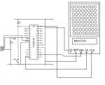
I then connected up my module to a 28x1 as per the diagram.
Then I tried to send the test display command to the screen, and, behold.. Some life.. The screen switches between 2 states.. I was expecting full screen on (all leds on) and then all leds off... But instead I get, one frame with few leds on, and the 2nd frame with some other leds on
bit confused regarding the correct layout for the command addressing and issuing.
data sheet says the serial data is 16bits... D15 to D0
When I write HSPIOUT (0X00,0X09) for example.. which side is the D15 side and which side is the D0 end?
to me HSPIOUT (0X00,0X09) is saying Decode mode = 0? or is is vicer versa?
is writing HSPIOUT (0x0,0x9) the same as above?
Any advice really appreciated.. And if anyone has a working example code I could learn a whole lot from it!
Hope everyone has a lovely weekend, and doesnt waste too much time for my posts!!
I know there are some recommendations for other post regarding these chips, but I cant seem to find anything that helps, or at least that I understand.
The clock examples etc that ive found are mainly for using the chips to drive 7 seg 8.-displays. I want to drive a 8x8 matrix.
I've read something about fake chips.. I hope mine arnt fake. I have 4 and they all seem to do the same thing..
The MAX7219 data sheet says "on initial power-up, all registers are reset / blank screen is shown" - This does not seem to be the case. All chips seem to startup showing some L.E.D on... humm?
Anyway, connected to a 28x1 to see if I could issue commands using the HSPIOUT command. After using the HSPISETUP.
HSPISETUP is a little confusing for me..
my chip -
on rising edge of CLK = 16bit shift into register
this should be regardless of LOAD?
CS should be low to clock data in or out
cs raising edge latches data
cs must go high during or after 16th clock pulse to latch the data.
So this information should result in my HSPISETUP configuration?
I used iny miny mo to guess I could use:
setfreq m8
hspisetup spimode00, spifast ; ??????????????????????? I chose spifast as set the internal clock to 8mhz?
I then connected up my module to a 28x1 as per the diagram.
Then I tried to send the test display command to the screen, and, behold.. Some life.. The screen switches between 2 states.. I was expecting full screen on (all leds on) and then all leds off... But instead I get, one frame with few leds on, and the 2nd frame with some other leds on
bit confused regarding the correct layout for the command addressing and issuing.
data sheet says the serial data is 16bits... D15 to D0
When I write HSPIOUT (0X00,0X09) for example.. which side is the D15 side and which side is the D0 end?
to me HSPIOUT (0X00,0X09) is saying Decode mode = 0? or is is vicer versa?
is writing HSPIOUT (0x0,0x9) the same as above?
Any advice really appreciated.. And if anyone has a working example code I could learn a whole lot from it!
Hope everyone has a lovely weekend, and doesnt waste too much time for my posts!!
Attachments
-
 24 KB Views: 105