der_fisherman
Member
Hi,
I am using a 28x1 PICAXE firmware level A.6, on a 28 Pin Project Board.
I am an almost total beginner with any sort of PICs though I was in the computer industry for almost 40 years. I was in hardware, but learnt assembler programming as well as BASIC (many years ago! For my O.U. courses). I programmed a lot in GWBASIC over the last 30 years (but not lately!), but for myself only.
My frustration is mostly with myself with regard to the I2C problems I am having.....
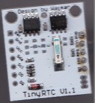
I want to control/use both a DS1307 RTC and an EEPROM 24C32. Both are mounted on the same tiny PCB. With a scope I can see the output LED signal of the RTC chip on the pin marked as SQ. This leads me to
believe that the RTC chip is working as designed.
I have added the necessary pullup resistors onto that tiny PCB, pulling sda and scl up to Vcc, using 4K7 resistors.
I read in the PICAXE Manual 1, it mentions for my chip that pins 13 and 14 (on the C output bank) are SCL and SDA respectively. But even writing to the RTC continuously in a tight loop, I was unable to
see any signals on those pins at all. I used a LED and a series resistor (as shown on PICAXE Manual 1 page 7), later with with an Oscilloscope. I am pretty sure that the PICAXE 28X1 is NOT outputting
anything on either of these two pins when using hi2cxxx commands.
I cannot find in any PICAXE documentation to do with I2C , a full 100% confirmation that these are the correct pins (14 & 15) to use (or not!).I suspect that they are.....and Rev-Ed staff kindly said they were as well. I trust his knowledge implicitly.
I am able to use the "C" outputs in other ways with no problems, setting them to outputs, outputting simple signals, all of which could be seen on the 'Scope screen. Just to be sure, I replaced the PICAXE chip twice with identical chips, no difference. Still no I2C activity to be seen.
The programs I wrote were accepted by the PICAXE Editor syntax checker, so the commands were correct for a 28X1 chip. Version 5.5.6. Not the Beta version.
I could also not get the pulsout command to work on the "C" outputs either.....though I only checked that with a LED, not with the 'Scope.
I also find that the documentation to be a bit strange (outdated?) in some puzzling (for me at least!) respects. If I look at I2C commands in the Manual part 2, I find newer commands such as Hi2cin,
i2cout and Hi2csetup with a partially good explanation, but also mentioning that "Use of I2C parts are in more detail in the separate I2C Tutorial" datasheet.
But in that sheet named "I2C Tutorial", no mention is made of any of the HI2Cxxxx list of commands, only ones like readi2c, i2cslave, writei2c. All of which are mentioned in PICAXE Manual 2 as being
"command is deprecated".......which I take as meaning it still works, but is not usually used anymore.......why is the "I2C Tutorial" datasheet not updated to reflect other, more update changes and commands?
Also, it would be helpful if the correct interfacing technique required for I2C usage was also documented in that datasheet. I just connected the two output pins to my PCB, where the pullup resistors are mounted. I connected the pins 14 & 15 to the RTC and EEPROM PCB, pins SDA, SCL and ground.
My personal take (as a beginner with PICs of any sort), is that the data sheet "I2C Tutorial", should be updated and have added the full hardware information for which pins are to be used for each and every PICAXE Chip......Short demo programs shown need to be commented with much more detail and newer commands also to be included. Leaving of course the older commands for those still using older chips of course.
I would also like to see in all manuals, that it is explicitly mentioned for which chips, which commands are used as some of the explanations near the Pin out diagrams are open to misunderstanding I feel.....
Please do not be upset with me, some of what I write here is probably wrong, for which I apologize, but as a beginner, floundering around for more than 4 days trying to make I2C do something! It is very frustrating.
I have to say that I still find that the PICAXE system to be one of the most exciting developments around that I have ever seen in my life, even though I am a relative latecomer to such technology. I am sure that many schools will be able to produce far more computer literate pupils than before and not forgetting the governments new trend on "coding" for schools, your products will be in even more demand in the UK and Ireland.
Well done is all I can say.
Many thanks in advance for any help given. I will be most grateful. I am sure its my lack of knowledge that gives me the problem(s).
Andy
Added later on Wednesday 12th March 08:00 MEZ/CET:-
I neglected to mention that I am using the PICAXE 28 Project PCB, with the 10K pullups still in place, do I need to remove this resistor pack, even though I can switch the inputs to outputs and make them high and low at will and see that on a scope screen.?
I am using a 28x1 PICAXE firmware level A.6, on a 28 Pin Project Board.
I am an almost total beginner with any sort of PICs though I was in the computer industry for almost 40 years. I was in hardware, but learnt assembler programming as well as BASIC (many years ago! For my O.U. courses). I programmed a lot in GWBASIC over the last 30 years (but not lately!), but for myself only.
My frustration is mostly with myself with regard to the I2C problems I am having.....
I want to control/use both a DS1307 RTC and an EEPROM 24C32. Both are mounted on the same tiny PCB. With a scope I can see the output LED signal of the RTC chip on the pin marked as SQ. This leads me to
believe that the RTC chip is working as designed.
I have added the necessary pullup resistors onto that tiny PCB, pulling sda and scl up to Vcc, using 4K7 resistors.
I read in the PICAXE Manual 1, it mentions for my chip that pins 13 and 14 (on the C output bank) are SCL and SDA respectively. But even writing to the RTC continuously in a tight loop, I was unable to
see any signals on those pins at all. I used a LED and a series resistor (as shown on PICAXE Manual 1 page 7), later with with an Oscilloscope. I am pretty sure that the PICAXE 28X1 is NOT outputting
anything on either of these two pins when using hi2cxxx commands.
I cannot find in any PICAXE documentation to do with I2C , a full 100% confirmation that these are the correct pins (14 & 15) to use (or not!).I suspect that they are.....and Rev-Ed staff kindly said they were as well. I trust his knowledge implicitly.
I am able to use the "C" outputs in other ways with no problems, setting them to outputs, outputting simple signals, all of which could be seen on the 'Scope screen. Just to be sure, I replaced the PICAXE chip twice with identical chips, no difference. Still no I2C activity to be seen.
The programs I wrote were accepted by the PICAXE Editor syntax checker, so the commands were correct for a 28X1 chip. Version 5.5.6. Not the Beta version.
I could also not get the pulsout command to work on the "C" outputs either.....though I only checked that with a LED, not with the 'Scope.
I also find that the documentation to be a bit strange (outdated?) in some puzzling (for me at least!) respects. If I look at I2C commands in the Manual part 2, I find newer commands such as Hi2cin,
i2cout and Hi2csetup with a partially good explanation, but also mentioning that "Use of I2C parts are in more detail in the separate I2C Tutorial" datasheet.
But in that sheet named "I2C Tutorial", no mention is made of any of the HI2Cxxxx list of commands, only ones like readi2c, i2cslave, writei2c. All of which are mentioned in PICAXE Manual 2 as being
"command is deprecated".......which I take as meaning it still works, but is not usually used anymore.......why is the "I2C Tutorial" datasheet not updated to reflect other, more update changes and commands?
Also, it would be helpful if the correct interfacing technique required for I2C usage was also documented in that datasheet. I just connected the two output pins to my PCB, where the pullup resistors are mounted. I connected the pins 14 & 15 to the RTC and EEPROM PCB, pins SDA, SCL and ground.
My personal take (as a beginner with PICs of any sort), is that the data sheet "I2C Tutorial", should be updated and have added the full hardware information for which pins are to be used for each and every PICAXE Chip......Short demo programs shown need to be commented with much more detail and newer commands also to be included. Leaving of course the older commands for those still using older chips of course.
I would also like to see in all manuals, that it is explicitly mentioned for which chips, which commands are used as some of the explanations near the Pin out diagrams are open to misunderstanding I feel.....
Please do not be upset with me, some of what I write here is probably wrong, for which I apologize, but as a beginner, floundering around for more than 4 days trying to make I2C do something! It is very frustrating.
I have to say that I still find that the PICAXE system to be one of the most exciting developments around that I have ever seen in my life, even though I am a relative latecomer to such technology. I am sure that many schools will be able to produce far more computer literate pupils than before and not forgetting the governments new trend on "coding" for schools, your products will be in even more demand in the UK and Ireland.
Well done is all I can say.
Many thanks in advance for any help given. I will be most grateful. I am sure its my lack of knowledge that gives me the problem(s).
Andy
Added later on Wednesday 12th March 08:00 MEZ/CET:-
I neglected to mention that I am using the PICAXE 28 Project PCB, with the 10K pullups still in place, do I need to remove this resistor pack, even though I can switch the inputs to outputs and make them high and low at will and see that on a scope screen.?
Last edited: