Trouble connecting 16x2 LCD to PICAXE20X2

jproehl

New Member
Hi:

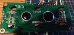
I am a newbie to the PICAXE and I'm having a problem trying to get a PICAXE20X2 to drive a 16x2 LCD. I saw a similar recent thread using a PICAXE 18M2 and an 8 bit connection, but I've wired mine up to operate in 4 bit mode. I've tried to code up the simple example from the PICAXE manual (modifying it for my different pin connections) and just get a line of square blocks on the LCD, which appear only on the second line of the LCD.

The data pins B.2-B.5 are connected to DB4-DB7 on the LCD, respectively, B.0 is connected to RS and B.1 is connected to ENABLE. I've attached my code and a photo of the LCD. In the initialization subroutine you'll see what may be a somewhat non-standard approach of shifting the two nibbles two places by multiplying or dividing by 4. This is done to match the result with the pin locations (i.e. so that the digits in each nibble map to the appropriate pins B.2-B.5). Hopefully it won't be too confusing, but I need to stick with this arrangement because once I get this to work, the PICAXE chip is going to pop into another circuit board that is hard wired with that pin usage. I've walked through the simulate function in the PICAXE editor watching the pins go high and low and believe that the proper pins are being activated. But, since the code is not working to correctly drive the LCD it could be a source of the problem.

I have my PICAXE20X2 mounted to an AXE118 board and I've added 8 pin headers to the 16 data pins on the two sides of the PICAXE20x2 to interconnect things. Let me know if you need to see a photo of that or anything else. I've also wired an off board 10Kohm potentiometer to adjust the backlighting for contrast adjustment of the LCD - that seems to work fine.

I'd appreciate any help anyone can provide as I'm totally lost at this point. Thanks!!
 

Attachments

Rick100

Senior Member
I think 'let b1 = 40' should be 'let b1 = 32'.

Edit:
Sorry. On a second look , I think 40 was correct. The 2 alternating lines showing up indicate the lcd is powering up but not initializing to 2 line mode. Do you have the write pin tied low?
 
Last edited:

marks

Senior Member
Hi jproehl ,
welcome to the forum.
I doubt wether you would be able to get that to work using pinsb will disrupt the rs and enable pins
you need to send separate bits this should work I just cut and paste from the code snippets area

Code:
#picaxe 20x2  '  4Bit Using Alternative pins marks
 SYMBOL DB7  = outpinB.5
 SYMBOL DB6  = outpinB.4
 SYMBOL DB5  = outpinB.3 
 SYMBOL DB4  = outpinB.2 
 SYMBOL E    = B.1  
 SYMBOL RS   = B.0  
 SYMBOL senddata  = b0
 SYMBOL index     = b1
      'value of count    = W1    ' b3,b2
      'display  count    = b4,b5,b6,b7,b8

      
      EEPROM 25,("Picaxe18M2")
      SETFREQ M32
 	dirsB = %11111111
 	dirsC = %11001111
 
Initialise: 	
	FOR  index = 0 to 6 
          LOOKUP index, ($33,$32,$28,$0C,$01,$02,$06),senddata : GOSUB Send    ' Initialise LCD/OLED
                       '(WakeUp)*3(Set4Bit)(4Bit/2Line)(DisplayOn)(Clear Display)(Return Home)(Entry Mode Set)
 	NEXT index : PAUSE 10
  
      DisplayHello:
            LOW  RS                                                                      ' commandmode
            senddata = 132 :                                     GOSUB Send              ' (128-147) Line 1 Cursor Position
           HIGH RS                                                                       ' charactermode
            senddata = "H" :                                     GOSUB Send
            senddata = "e" :                                     GOSUB Send
            senddata = "l" :                                     GOSUB Send
            senddata = "l" :                                     GOSUB Send
            senddata = "o" :                                     GOSUB Send
pause 10000
            LOW  RS                                                                      ' commandmode
            senddata = $01 :                                     GOSUB Send : PAUSE 10   ' Clear Display
            senddata = 192 :                                     GOSUB Send              ' (192-211) Line 2 Cursor Position
           HIGH RS                                                                       ' charactermode 
           FOR  index = 25 to 34
           READ index, senddata :                                GOSUB Send              ' sending character    
 	     NEXT index 
pause 4000

      Count1:
            LOW  RS                                                                      ' commandmode 
            senddata = 202 :                                     GOSUB Send              ' (192-211) Line 2 Cursor Position
      HIGH RS                                                                            ' charactermode 
      INC W1                                                                             ' add to W1
           BinToAscii W1,b8,b7,b6,b5,b4
           FOR  index = 0 TO 5                                                           ' sending characters
 	     LOOKUP index,(" ",b8,b7,b6,b5,b4),senddata :          GOSUB Send                 
           NEXT index
      PAUSE 8000                                                                         ' 1 second (M32)   
            
goto count1

       Send:
         DB7 =   bit7    	
         DB6 =   bit6    	
         DB5 =   bit5    	
         DB4 =   bit4   	
        PULSOUT E,1 
         DB7 =   bit3   	
         DB6 =   bit2    	
         DB5 =   bit1    
         DB4 =   bit0   	
        PULSOUT E,1        :                                     RETURN
 

hippy

Ex-Staff (retired)
I doubt wether you would be able to get that to work using pinsb will disrupt the rs and enable pins
That can be a problem but should work in this case. The pinsB= commands set RS and E low, then the HIGH/LOW RS and PULSOUT E will set them to the required levels.

The issue is probably in the LCD initialisation sequence.

It would probably be easier to use your own example code ( or other code on the forum ) which has been designed to control LCD's in 4-bit mode using any pins than trying to adjust the example in the manual.
 

westaust55

Moderator
@jproehl,
Firstly Welcome to the PICAXE forum.

Is there any particular reason for using 4 pins in the middle of the portB rather than the high or low nybble on the destination boards?
Irrespective is should work. But it is not to avoid the i2c pins, maybe the Hserin/Hserout pins being used for another function ?

The initialisation sequence differs from what I normally use (including my DCC Accessory decoder project posted last week).

Here is an extract of your initialisation sequence based on your code with the sequence of some values changed that you can try.
Note I have use hexadecimal values as they can be far clearer for both you and use the readers/helpers than decimal in knowing what bits are set ($F0 is immediately seen whereas 240 makes on think more).

Code:
LCD_init: 
	pause 500 			' Wait 500ms for power stabilization 
	let dirsB = %11111111	' Set all B pins (B.0-B.7) as output lines for LCD
	let pinsB = %00001100	' Set pin B.2 and B.3 HIGH (others LOW) for 8-bit operation
	pulsout ENABLE,1 		' Send data by pulsing ?enable?
	pause 10 			' Wait 10 ms
	pulsout ENABLE,1 		' Send data again
	pause 200 			' Wait 200 ms
	pulsout ENABLE,1 		' Send data again
	pause 10 			' Wait 10 ms
	let pinsB = %00001000	' Set pin B.3 HIGH (others LOW) for 4-bit operation
	pulsout ENABLE,1 		' Send data by pulsing ?enable?
	let b1 = $28		' Set LCD code to $28 Display Format
	gosub wrins 		' Write instruction to LCD
	pause 100 			' Wait 100 ms
	let b1 = $0C	 	' Set LCD code to $0C for Display On
	gosub wrins 		' Write instruction to LCD
	pause 100 			' Wait 100 ms
	let b1 = $06	 	' Set LCD code to 6 for Cursor to move 
	gosub wrins 		' Write instruction to LCD
	pause 100 			' Wait 100 ms
	let b1 = $01	 	' Set LCD code to 1 for clear display instruction
	gosub wrins 		' Write instruction to LCD
	pause 100 			' Wait 100 ms
	return

wrchr: let b2 = b1 & $F0 / 4	' Mask the high nibble of b1 into b2 and shift for pin locations
	 let b3 = b1 & $0F * 4	' Mask the low  nibble of b1 into b3 and shift for pin locations
last 2 lines are included here just to demonstrate that $F0 instantly to many of use indicates the upper 4 bits whereas decimal 240 takes more thought.

Here is an extract (passes syntax check but not testing in actual hardware as extracted) from my recent project for a 20X2 operating at 64 MHz with a 16x2 display using 4-bit mode B.4 to B.7 and the Enable on pin C.0 plus RS on C.1.
Consider or ignore as you see fit:
Code:
; -----[ PICAXE Pin Allocation Diagram]-------------------------------------------------
; 
;
;                          PICAXE 20X2
;                         +----\_/----+
;                         |           |
;                     +5V |1       20 | Gnd
;                         |           |
;           Prog_SerialIn |2       19 | A.0 ProgSerOut
;                         |           | 
;Dir_485     - Output C.7 |3       18 | B.0 Input  - Keypad R1 (with pullup)
;                         |           |
;Rx_485+Diode - Input C.6 |4       17 | B.1 Input  - Keypad R2 (with pullup)
;                         |           |
;Tx_485      - Output C.5 |5       16 | B.2 Input  - Keypad R3 (with pullup) 
;                         |           |
; Spare IO            C.4 |6       15 | B.3 Input  - Keypad R4 (with pullup)
;                         |           |
; Spare IO            C.3 |7       14 | B.4 Output - Keypad C1 / LCD Data4
;                         |           |
;CabBus_Activity_LED  C.2 |8       13 | B.5 Output - Keypad C2 / LCD Data5
;                         |           |
;LCD_RegSel  - Output C.1 |9       12 | B.6 Output - Keypad C3 / LCD Data6
;                         |           |
;LCD_Enable  - Output C.0 |10      11 | B.7 Output - Keypad C4 / LCD Data7
;                         |           |
;                         +-----------+
;
;
#PICAXE 20X2
;#NO_DATA
;
; -----[ I/O Definitions ]-----------------------------------------------------------
; Define Input & Output discrete pin assignments
;	SYMBOL PC_Out	= A.0
;	SYMBOL KeyRow1	= B.0
;	SYMBOL KeyRow2	= B.1
;	SYMBOL KeyRow3	= B.2
;	SYMBOL KeyRow4	= B.3
;	SYMBOL LCDData4 	= B.4		; LCD Data Line 4 ==> LCD Pin 11
;	SYMBOL LCDData5	= B.5		; LCD Data Line 5 ==> LCD pin 12
;	SYMBOL LCDData6	= B.6		; LCD Data Line 6 ==> LCD pin 13
;	SYMBOL LCDData7	= B.7		; LCD Data Line 7 ==> LCD pin 14

 	SYMBOL Enable	= C.0		; 0 = Idle      1 = Active
	SYMBOL RegSel	= pinC.1	; 0 = Command   1 = Data
	
;
; -----[ LCD Related Constants assignment ]-------------------------------------------
;
	SYMBOL RSforCmd	= 0 		; Select Command register
	SYMBOL RSforData	= 1 		; Select Data register
	SYMBOL LCDLine1L	= $80		; command to place cursor at start of line 1
	SYMBOL LCDLine1R	= $88		; command to place cursor at 9th char on line 1
	SYMBOL LCDLine2	= $C0		; command to place cursor at 12th char on line 2
	SYMBOL CursorLeft = $10		; command to move cursor left 1 character
	SYMBOL Space	= $20		; LCD space code
;
;	
;
; -----[ Delay and communications Constants assignment ]-----------------------------
; 
	SYMBOL Dly15ms	= 120		; 15 msec period at 64 MHz with the PAUSE command
	SYMBOL PulsDur	= 8		;  8 ==>  10 us duration at 64 MHz with PAUSEUS command
;
; -----[ Variables assignment ]------------------------------------------
;
	SYMBOL Char		 = b10	; next byte of data/ command to LCD
	SYMBOL CharPtr	 = b11	; FOR...NEXT index for next EEPROM/TABLE memory location to fect for sending to LCD
	
;========================================================================================
;
; -----[ EEPROM Data for LCD Init and LCD Messages ]------------------------------------------
;
; LCD display message data - held in EEPROM (total of 256 bytes avilable in the 20X2)
;
; Note EEPROM bytes 0 to 5 are used for the LCD initialisation sequence
; DO NOT CHANGE THESE

; Nibble commands - To initialise LCD into 4-bit mode
	EEPROM 0, ($33)			; %0011---- %0011----   8-bit / 8-bit
	EEPROM 1, ($32)			; %0011---- %0010----   8-bit / 4-bit
;
; Byte commands - To configure the LCD
	EEPROM 2, ($28)			; %00101000 %001LNF00   Display Format
	EEPROM 3, ($0C)			; %00001100 %00001DCB   Display On
	EEPROM 4, ($06)			; %00000110 %000001IS   Cursor Move
						;
						; L : 0 = 4-bit Mode    1 = 8-bit Mode
						; N : 0 = 1 Line        1 = 2 Lines
						; F : 0 = 5x7 Pixels    1 = N/A
 						; D : 0 = Display Off   1 = Display On
						; C : 0 = Cursor Off    1 = Cursor On
						; B : 0 = Cursor Steady 1 = Cursor Flash
						; I : 0 = Dec Cursor    1 = Inc Cursor
						; S : 0 = Cursor Move   1 = Display Shift
	EEPROM 5, ($01)			; Clear Screen
	EEPROM 6, ($0F)			; Turn Cursor On and Flashing 
;


;********************************************************************************************
; PROGRAM STARTS HERE
;********************************************************************************************
;
; Initialisation sequence to configure the LCD display, show first intro message and
; check if the CAB address is to be changed
Initialise:
	SETFREQ m64
		
	dirsB = %11110000 				; Set PortB pins 4 to 7 as Outputs
	dirsC = %10000111					; Set PortC pins 0 to 2 & 7 as Outputs -DO NOT set the SEROUT pin

	GOSUB InitialiseLcd

	
	DO
	
	LOOP
	END
	

;========================================================================================
; Subroutine to initialise the LCD using 4-bit parallel interface
InitialiseLcd:
	FOR CharPtr = 0 TO 5
	  READ CharPtr, Char
	  GOSUB SendInitCmd2LCD
	NEXT
	PAUSE Dly15ms					; Further 15 ms delay needed at 64 MHz
	RETURN

; Subroutine Entry Point for initialising the LCD
SendInitCmd2LCD:
	PAUSE Dly15ms					; Delay 15mS to allow time for LCD to do initialisation

; Subroutine Entry Point for Sending Commands
SendCmd2LCD:
        RegSel = RSforCmd				; Set RS pin for Command as next byte

; Subroutine Entry point for Sending Data/Characters to the LCD
SendData2LCD:
	pinsB = Char AND $F0				; Put high nybble out first on top 4 pins of Port B
	PULSOUT Enable, PulsDur				; Give a 10uS pulse on Enable Pin
	pinsB = Char << 4					; Put low nybble out second on top 4 pins of Port B
	PULSOUT Enable, PulsDur				; Give a 10uS pulse on Enable Pin
	RegSel = RSforData     				; Set the RS pin for sending Data bytes 
	RETURN
Forum Member Marks has also in the past posted code for LCD operation in 4 and 8 bit modes in a thread he started should you wish to search for same.
 

jproehl

New Member
I think 'let b1 = 40' should be 'let b1 = 32'.

Edit:
Sorry. On a second look , I think 40 was correct. The 2 alternating lines showing up indicate the lcd is powering up but not initializing to 2 line mode. Do you have the write pin tied low?
Hi, thanks for your reply. I do have R/W, and DB0-DB3 all tied low.
 

jproehl

New Member
Hi:

Thanks for all of your replies and suggestions. I copied the codes provided and will try modifying them to my pin designations and see if they work for me.

By the way, what great response times, this Forum is a great resource!

Jeff
 

jproehl

New Member
That can be a problem but should work in this case. The pinsB= commands set RS and E low, then the HIGH/LOW RS and PULSOUT E will set them to the required levels.

The issue is probably in the LCD initialisation sequence.

It would probably be easier to use your own example code ( or other code on the forum ) which has been designed to control LCD's in 4-bit mode using any pins than trying to adjust the example in the manual.

I had thought of getting code from the forum to start, but couldn't find any that seemed appropriate at the time or that I could understand well enough to modify. I decided that the first LCD example in the manual was simply enough that even I could understand and learn from it. Thanks!
 

Rick100

Senior Member
Hello,

I had an LCD screen on my axe091 board so I tried your code. The 1st run through the screen went blank, indicating that it was initializing. After a couple of changes the following code works. Your program was mostly correct. The major problem was the instruction to turn the screen on was turning it off. A couple of other minor changes. If you try it and the screen remains with the 2 lines of blocks, I would recheck the wiring.

Code:
' Simple test program for driving a 16x2 LCD
'
' RS is connected to pin B.0 ... RS=0 Command mode, RS=1 Character mode
' ENABLE is connected to pin B.1
' DB4 is connected to pin B.2 ... 4th binary digit in nibble
' DB5 is connected to pin B.3 ... 3rd binary digit in nibble
' DB6 is connected to pin B.4 ... 2nd binary digit in nibble
' DB7 is connected to pin B.5 ... 1st binary digit in nibble

symbol RS = B.0
symbol ENABLE = B.1

EEPROM $00,("ACME Industries")  ' store the text in the EEPROM memory
EEPROM $10,(" Welcomes you! ")  ' store the text in the EEPROM memory

gosub LCD_init 			  ' initialize Output pins and the LCD

main: let b1 = 1 			' set b1 to "clear display" instruction
	gosub wrins 		' send instruction to LCD
	
	
'	for b4 = 0 to 15 		' setup for...next loop ("ACME Industries" - positions 0 to 15)

'**********************************

	for b4 = 0 to 14 		' setup for...next loop ("ACME Industries" - positions 0 to 15)
		read b4, b1 	' read letter from EEPROM into variable b1
		gosub wrchr 	' send character to LCD
	next b4 			' next loop
	
	let b1 = 192 		' set b1 to start of second line position
	gosub wrins 		' send instruction to LCD
'	for b4 = 16 to 31 	' setup for...next loop (" Welcomes you! " - positions 16 to 31)
'**********************************

	for b4 = 16 to 29 	' setup for...next loop (" Welcomes you! " - positions 16 to 31)
		read b4, b1 	' read letter from EEPROM memory into variable b1
		gosub wrchr 	' send character to LCD
	next b4 			' next loop
      stop

LCD_init: 
	pause 500 			' Wait 500ms for power stabilization 
	let dirsB = %11111111	' Set all B pins (B.0-B.7) as output lines for LCD
	let pinsB = %00001100	' Set pin B.2 and B.3 HIGH (others LOW) for 8-bit operation
	pulsout ENABLE,1 		' Send data by pulsing ?enable?
	pause 10 			' Wait 10 ms
	pulsout ENABLE,1 		' Send data again
	pause 200 			' Wait 200 ms
	pulsout ENABLE,1 		' Send data again
	pause 10 			' Wait 10 ms
	let pinsB = %00001000	' Set pin B.3 HIGH (others LOW) for 4-bit operation
	pulsout ENABLE,1 		' Send data by pulsing ?enable?
	let b1 = 40			' Set LCD code to 40 for 4-bit, 2 lines operation.
	gosub wrins 		' Write instruction to LCD
	pause 100 			' Wait 100 ms
	
	'let b1 = 8	 		' Set LCD code to 14 for Screen on, cursor on instruction
'************************************************
'this was probably your biggest problem as the screen was turned off

	b1 = 14
	gosub wrins 		' Write instruction to LCD
	pause 100 			' Wait 100 ms
'*************************************************
'put it before clear screen command although I'm not sure it matters

	let b1 = 6	 		' Set LCD code to 6 for Entry mode instruction
	gosub wrins 		' Write instruction to LCD
	pause 100 			' Wait 100 ms	
	
	
	let b1 = 1	 		' Set LCD code to 1 for clear display instruction
	gosub wrins 		' Write instruction to LCD
	pause 100 			' Wait 100 ms

	return

wrchr: let b2 = b1 & 240 / 4	' Mask the high nibble of b1 into b2 and shift for pin locations
	 let b3 = b1 & 15 * 4	' Mask the low  nibble of b1 into b3 and shift for pin locations
	 let pinsB = b2		' Bring pins for shifted high nibble of b_1 high
	 high RS 			' Make sure RS is high before sending characters
	 pulsout ENABLE,1 	' Pulse the ENABLE pin to send data.
	 let pinsB = b3 	 	' Bring pins for shifted low nibble of b_1 high
	 high RS 			' Make sure RS is high before sending characters
	 pulsout ENABLE,1 	' Pulse ENABLE pin to send data.
	 return
	 
wrins: let b2 = b1 & 240 / 4	' Mask the high nibble of b1 into b2 and shift for pin locations
	 let b3 = b1 & 15 * 4	' Mask the low  nibble of b1 into b3 and shift for pin locations
	 let pinsB = b2 	 	' Bring pins for shifted high nibble of b_1 high
 	 low RS 			' Make sure RS is low before sending instruction
	 pulsout ENABLE,1 	' Pulse the ENABLE pin to send data.
	 pause 10 			' Wait 10 ms
	 let pinsB = b3		' Bring pins for shifted low nibble of b_1 high
	 low RS 			' Make sure RS is low before sending instruction
	 pulsout ENABLE,1 	' Pulse ENABLE pin to send data.
	 pause 10 			' Wait 10 ms
	 high RS 			' Set RS to high to return to character mode
	 return
Good luck,
Rick
 
Top