Transistor help

Hello all!
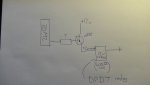
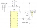
I was wondering if anyone could help me, for my systems a level project I need to switch on a relay with a PICAXE. I have tried to connect a pin on chip to a resistor which goes in to a darlington pair transistor. Which 12v is connected to its collector, then the collector through the relay and then to ground.


I have tried with all sorts of values of resistors on the base(remember I have 5) and Nottingham worked. Is there another solution or what can I do. I appreciate all your help. :)
 

srnet

Senior Member
I thought Nottingham was in Nottingamshire ?

Can you give us the circuit you have connected up ?

Pencil paper and a picture will do
 
I thought Nottingham was in Nottingamshire ?

Can you give us the circuit you have connected up ?

Pencil paper and a picture will do
Thank you for the reply, I have taken a picture of what I am hopefully going to create, if there isn't a solution, I can always resort to buying a smaller relay(But hopefully not!)(The dpdt 5v relays from maplin) P.S If you could recommend a transistor that would be incredibly awesome :) I cant remember of the top of my head but I know this is a darling ton pair transistor. (I am assuming this just means it has a higher gain). Thanks again!
S1010031.JPG
 

russbow

Senior Member
Have a look at manual 3, page 6.

If you are using this type of circuit, and it doesn't work, then maybe your program needs looking at.
 

womai

Senior Member
You are trying to implement a high-side switch. Problem is, the moment current starts flowing through the relay coil it will cause the transistor to "float up", and driving the base will no longer work because it floats up, too, so there is no longer a positive voltage difference between the Picaxe output (sitting at 5V) and the transistor's base. Slightly simplified but gives you the idea.

Simple solution, implement low-side switching instead, i.e. put the relay coil in the collector path (instead of the emitter path), with emitter connected to ground, and it will work just fine.
 

JimPerry

Senior Member
And use a diode accross the relay coil (Cathode to positive) to protect the transistor when the relay turns off. :confused:

EDIT : I typed it backwards first time - sorry:)
 
Last edited:

thomasfoltz

New Member
I hope this will help in why this circuit won't work right. Think of the base->emitter pins as a diode. You are feeding the base with 5 volts, which would be the anode of that diode in the transistor. There is a voltage drop of about 0.7 volts across that diode, so you will have just over 4 volts at the emitter pin going to drive a 12 volt relay coil. That is with a single transistor. You put a Darlington transistor in there and you have two base->emitters to go through, leaving less than 4 volts at the emitter, not enough to drive the relay coil. Think of a transistor as two diodes tied together. The base is created with the two anodes tied together for an NPN, one cathode is the emitter and the other cathode is the collector. Tie two cathodes together to make a PNP. One anode for the collector and the other anode for the emitter. You cannot defeat Ohms Law, even with a transistor.
 

Pat13

Senior Member
Not trying to hijack this thread, but I have a transistor question. I am using a 18M2 to call up files on a Tenda mp3 module and to monitor the "busy" pin of the tenda in a do:loop. I want to use this PNP transistor http://www.taydaelectronics.com/2n2907a-2n2907-pnp-transistor-60v-0-6a-to-18.html to switch a 12V relay by using the "busy" pin on the tenda (pin goes low and switches on transistor). I have a 470 Ohm resistor between the "busy" pin and the base of the transistor. Collector goes to 12V, emitter goes to relay. When the Tenda is busy, the relay switches on, but when the busy pin goes high, the relay is still energised. It is only when the pin is high for a considerable time (>7 seconds) does the relay switch off. Any suggestions?
 
Top