Touch Switches

ZOR

Senior Member
I have just found I cannot get switches in a remote control box, and wondered if touch switches can be made easily. I thought at first I could just have 4 raised bolt heads, but then reading posts found you must not touch them? I seem to remember a similar to bolthead, a split where your finger bridged accross.

I am wanting something presentable to replace switches, any ideas, thanks
 

ZOR

Senior Member
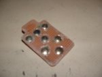
Just read a PICAXE FAQ. IF I have a strip of veroboard mounted track uppermost underneath my plastic case top which is about the same thickness as a printed circuit board and drilled out islands in the track, would it work? Anybody done it?

Also, would I need to use screened cable back to my PCB?

Thanks
 

SD70M

Senior Member
I tested out the touch facility on a 20M2 and it senses to a piece of unstripped wire so no reason why a piece of veroboard can't do the same thing.

Angie
 

ZOR

Senior Member
Thanks Angie. I did think about drilling holes about half an inch apart and running wire out then back in, forming a tight raised loop. I just wonder what/if there will be any problems with false pickups when handling the remote controller case, hence wondering if my return to the Picaxe should be screened.

Thanks again
 

Paix

Senior Member
I believe, but don't know, that an earth ring around the touch sensor pads will help to better define the touch area and mitigate against bleed from out of the area.

Perhaps someone authorative soul can confirm or contradict this idea?
 

ZOR

Senior Member
Many thanks. I think thats probably a very good idea and easy to make with veroboard. I can make my 4 touch areas be surrounded by an earthed matrix. Not knowing the theory behind it, I don't know if the idea is to form a link to ground via a non touching finger. As you say, maybe somebody with knowledge could possibly look in a give a few hints. Thanks again
 

eclectic

Moderator
Many thanks. I think thats probably a very good idea and easy to make with veroboard. I can make my 4 touch areas be surrounded by an earthed matrix. Not knowing the theory behind it, I don't know if the idea is to form a link to ground via a non touching finger. As you say, maybe somebody with knowledge could possibly look in a give a few hints. Thanks again
Lots of info out there.

Use Advanced Search
and the terms

touch sensor*

One of many.
http://www.picaxeforum.co.uk/showthread.php?15966-First-observation-about-TOUCH16-on-18M2&highlight=touch


e
 

ZOR

Senior Member
Such a wide range of posts, some covering having to calibrate, some saying you bridge two contacts, then warnings not to directly touch. Too many things to read, nothing direct as to pad spacing, dealing with wires back to Picaxe (ie any interference/pickup likely) I was going to just play but now going to source smaller switches, far easier. Thanks
 

eclectic

Moderator
Such a wide range of posts, some covering having to calibrate, some saying you bridge two contacts, then warnings not to directly touch. Too many things to read, nothing direct as to pad spacing, dealing with wires back to Picaxe (ie any interference/pickup likely) I was going to just play but now going to source smaller switches, far easier. Thanks
Don't leave it yet.

Play.

It'll cost nothing to connect a few washers
and cover them with sticky tape.

Wood and trees mate. :)

e
 

ZOR

Senior Member
OK I will give it a try, you have twisted my arm.
I looked in manual 3, interfacing to Picaxe and found nothing or was it me? However in coding examples, under touch and touch 16 it gives more information. Don't know why I saw nothing in the interfacing bit?

What worries me is many times I get things working in a breadboard state, but when I try to make a finished presentable version it does not work. So anything that's hit or miss I steer clear of, learnt that after getting married!!

So I will give it a go tomorrow, thanks.

Wood and Trees? Does that mean not being able to see the wood for the trees?

Regards
 

ZOR

Senior Member
Many thanks eclectic for the push.
Tried it out, and yes it's good. I can understand how it works now and how to setup it's trip level (b0)

08M2

Code:
main:
touch C.4,b0 
DEBUG
if b0 > 50 then
high C.2 
else
low C.2
endif
goto main
I put in DEBUG so I could see my particular output from my touchpad, which was an island on a veroboard strip. I will now put veroboard underneath my plastic box lid, and add some placement markings. Excellent, thanks again
 

Paix

Senior Member
I have to say that debug I rarely use, it's too blunt an instrument and I believe has more processing overhead (time).

If you know what variable you want to monitor. sertxd (b0, " ")

I would use RG174 coax or a thin microphone cable to e's washer. Others have used coins, which might be a cheaper option than wires and be more readily available in your pocket :). The screen is earthed at the board end and insulated next to the washer so that no interference can be picked up by the connecting wire.
 

ZOR

Senior Member
Thanks paix, yes I will use mic cable as I found the wires can be sensitive. I am using veroboard (stripped copper) drilling away track to leave islands. I am mounting this directly under my remote box top. I am going to drill the smallest hole I can do in the centre of each pad in the case top which will be my finger guide and too small for skin depression to go through, takes away bothering with transfers that will rub away.

So all in all should work out fine. I will move to using sertxd.

Thanks again
 

jinx

Senior Member
hi,
have you consided using brass drawing pins. I've had good results using them just solder a wire on them then connect to the pin then hot glue or even super glue them to the case.
 

SD70M

Senior Member
@Zor

Glad you got it sorted. Does each pad require an earth around it to stop to touch sensors activating at the same time when close together? Or is there a 'required' distance between them?

I never got that far :)

Angie
 

ZOR

Senior Member
Because of space, I have got quarter of an inch space at worst between each pad, I think it will should be okay because when I tested one pad I could do other things around the pad and it did not cause a problem. I found the pad size is quoted in manual 2, but did not see spacing. I have ommited an earth surround pads layout for now to see if I really need it. Being able to set the ADC value helps a lot because you can appear to play with it's trip level. I did find that if you touched the connecting wires sleeving it would switch, so certainly I will use screened wire. I was going to try 4 core screened for the 4 switchpads, but maybe the emf of one active wire would interfere with the others. Will have to try that. See how it goes. Thanks again
 

Paix

Senior Member
The preferred cable is RG174 or RG178 coax, which is around 0.1 inch diameter and ideal for shielded leads inside cabinets and between and indeed on boards where a screened connection is required.

It's the sort of stuff that everyone could do with a couple of metres in the bits box as it's invaluable. I have a few metres of it in a ziplock bag, somewhere, if I can ever find it . . . :)
 

ZOR

Senior Member
Thank you paix, I was going to try multicore single screen, but wondered if there might be interwire problems.

I like the idea of drawing pins jinx, but I thought it was a big no no to touch the Picaxe connections, had to be isolated under tape etc.
 

SD70M

Senior Member
Thank you paix, I was going to try multicore single screen, but wondered if there might be interwire problems.

I like the idea of drawing pins jinx, but I thought it was a big no no to touch the Picaxe connections, had to be isolated under tape etc.
I think paix meant glue the drawing pins inside your enclosure where you want to touch-control at. Then solder wires to each of the pins.

No reason why you couldn't push the pins through a thin piece of plastic, then solder wires to the pin, and glue the drawing pin to the plastic, then use that inside your enclosure.

Angie
 

westaust55

Moderator
Untested, but my theory would be that as the TOUCH sensors work by capacitive means, putting an earthed ring around the primary sensor pad would act as a capacitive pre-load on the TOUCH input.
This would be a relatively consistent capacitance if the space from ring to sensor is constant for each sensor.
However, even with such an earthed ring, putting your finger over one sensor could still have a small influence on any other relatively close SENSOR pad.

It would be a case of ascertaining the value the TOUCH command receives when the desired sensor is "touched" (through an insulating medium) and setting the setpoint to be high enough to exclude any slight rise on adjoining sensors and still having a TOUCH input value above the setpoint so it is registered.
 

ZOR

Senior Member
Thanks, I seem okay so far without earthed ring. As you say, it would play no involvement towards a finger above.
A wire connected to a drawing pin is a good idea but is it wrong in direct touching? "touched" (through an insulating medium)
 

ZOR

Senior Member
Thanks Jinx, very good.

I have just found if I hold one leg of a 100pf connected to touch input pin, I get a full value of 255 appearing in my b0 variable. I tried other values ie 220pf, where I got 255 to begin with for a second, and then dropping to zero.

Is this allowed, consistant or just random. It would be easy to use boltheads as touch points connected via capacitors.

Thanks

Edit: Just tried 2 220pf capacitors in series, got ADC value 255, then held center juction of the 2 capacitors ie 220pf, and got as before 255 to start dropping to zero after 1 second.

So am I tuning something?
 

jinx

Senior Member
haa,
never used the cap that way " and dont think i would " because your still touch'in a bear sensor which according to all the manuals i,ve read and tech say it's a noo leads too unreliable use.
bolthead sould work but can you solder a good joint to it!. got any brass washes.
 

ZOR

Senior Member
Thanks. All the indirect touch methods are of capacitance nature (might be talking out of the back of my head?)
Holding one end of a capacitor lead should be indirect, as the capacitor is 2 plates. (Disc Ceramic)
I am still working on my veroboard panel, but getting a low value ADC 12/15 because of spacing from finger (case top wall thickness)

Another idea I had which sadly did not work was using the finger proximity to an LED. I had hoped I could have used it as a capacitance device which would have then lit.

Anyway I am still playing.

Regards
 

SD70M

Senior Member
I am still working on my veroboard panel, but getting a low value ADC 12/15 because of spacing from finger (case top wall thickness)
How thick is the case!!!! Someone on here managed to get touch to work through 6mm glass recently. (Sorry to whoever you are, memory's as old as I am ;) )

Angie
 

ZOR

Senior Member
All in all it's about 4.5mm to the copper track. It does work even though ADC is low, I was curious as to why if it's capacitance between me and the Picaxe then why something with direct contact cannot be used with a capacitor to the Picaxe.
It's just trying to get something that does not look made from a junk box. Thanks
 

eclectic

Moderator
Print your pretty switch pattern on thin card.

Lay it over the washers then laminate
or use wide sellotape.

Looks good and insulates as well.

e
 

SteveT

Senior Member
OR beg or borrow some clear nail varnish from a female member of the family and insulate with that. Sorry, that makes me look as old as I am....... these days it could quite well be a male member of the family that uses the nail varnish.... or perhaps you have some yourself :rolleyes: <big tongue in cheek>
 

Paix

Senior Member
Shows what you know about nail varnish SteveT :) (not trying to bluff are you? :) ). It might attack the plastic case. Similarly if drawing pins were pushed through plastic and then soldered to. I would solder to the drawing pins and then stick to the underside of the plastic if using drawing pins. It was Jinx that suggested the pins Angie, not me, but thanks for the credit anyway, I need it :)
 

ZOR

Senior Member
Thanks all. I was starting to lose interest and have ordered switches. Sorry I gave it a good try. I tried different things, soldering on the back of SIM cards, using PCB standoff pillars that had screw entry from both ends that never touched, hoping the capacitance between the two bolts could be used. I then found that if I turned my PCB pad switch 90 degrees then my ADC value nose dived, almost as though the control wire was hum bucking. Hope hum bucking still valid in dictionary, almost picking up hum (50hz) and phase cancelling. As my unit is hand held I don't want if's.

Anyway it was a good exercise, sure to be used in the future.

Thanks everyone.
 

jinx

Senior Member
hi
dont give up on the touch! I never asked but you are using an M2 picaxe. you got any pic's of the touch board you made " i'll still harp on about using the drawing pins there so easy to add drawing pin to inside of case -- short as possible wire -- female header con -- then connect that to a male header pin on your project board " bob's your uncle you have touch".

It was Jinx that suggested the pins Angie, not me, but thanks for the credit anyway, I need it
LOL:rolleyes:
 

jinx

Senior Member
hi,
NP SD70M the idea of using drawing pins were floated around the forum before I used them, but now if i need a touch input i stick a pin on.
 

ZOR

Senior Member
Thanks jinx. I do agree your drawing pins are a good idea, it's just the thought the concept is relying on possibly picking up noise, or capacitance to ground. I have done so many lashups in the past, that when assembled as professional as I can, don't work, resulting in ripping to pieces and never fully getting same results. Yes in some instances touch switches look good, and as I say I don't feel I have wasted time in trying out things. However I can't wait for my nice little switches to arrive, work every time, no possible interactive wiring problems, lovely click click.

If it was as easy as it used to be to buy perspex locally cut to size , I would have devised something presentable under perspex. Never mind, 2 days (trees and woods)
 

jinx

Senior Member
hi,
it's just the thought the concept is relying on possibly picking up noise, or capacitance to ground
in your overall project?or with touch? I just can't see them being an issue the touch feature does make use of internal oscillator of the M2 but it's never givin the overall project problem " my programming does but not touch ". Stop looking too hard at. Am building a serial touchpad " been on the bread board for months " with the idea if i need touch I can just plug into the main proccessor. I shold post it, but am all over looking to build the prussa mendel at the mo.
 

Paix

Senior Member
I had to Google for Prussa Mendel of course, but it's a RepRap machine, if I'm allowed to say that. Good luck with the project.

I don't know if Lazlo Biro would have taken offence if asked if he had a Bic on him or not :)
 
Top