Toothbrush induction charger

dennis

Member
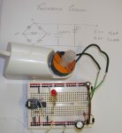
These could be useful for lower power Picaxe projects. I wound a coil on a simple plastic former to drop over the Braun charger. (wire diameter 0.25mm coil resistance 8 ohm ). The coil AC is rectified with 4 standard diodes in the usual bridge layout.

The DC output is about equivalent to a 24V source with 680 ohm internal resistance.
At 9.7V about 14.5 mA is available and at 4V around 24 mA. I have used a zener (assumed around 5V) directly across the bridge output to prevent damage to the Picaxe.
An 08M has been running overnight flashing LEDs and working a piezo sounder without problems.

I had hoped to use this arrangement both to power a Picaxe as well as to provide a mains frequency timing pulse but unfortunately the induction frequency is much higher than 50Hz.

Hope this can be of some use to someone.
 

Attachments

westaust55

Moderator
Good idea there. The topic of wireless/inductive power has been raised before but have not seen posts of anyone putting it into practice.

How many turns in the coil placed over the toothbrush charger?

a warning, those stereo programming sockets have relatively short leads and can cause grief when plugged directly into a breadboard as shown in your photo. Suggest move the plug only to a piece of proto-board and use header pins for better contact with the breadboard.


Edit:
try using the count command from a PICAXE for 1 second to ascertain the base unit frequency?
Could then use a 4040 or similar divider/binary counter chip to bring it down to a "usable frequency if too high
 
Last edited:

gengis

New Member
http://zekfrivolous.com/faq/REPAIR/samschem.htm#schras4

Has a schematic of the mains operated oscillator as well as the battery circuit. "Electric Toothbrush with Inductively Coupled Charger" for Interplak Model PB-12 electric toothbrush.

The Ultrasonic Cleaner circuit could probably be adapted for a higher power version of the toothbrush charger with little modification.
 

dennis

Member
I should have made up a (Picaxe based of course) counter when winding the coil. The coil section is roughly 12mm by 3mm. The winding was not layer by layer like a professional coil and the packing density is maybe not very high. As a start guess as the wire is 0.25mm diameter 48 by 12 or about 600 turns might be about right

The wire is very strong so the winding process was easy.

Thanks for the warning on the stereo socket. I had trouble before and shaved the black plastic locator pins off the bottom and stuck it in place with a drop of super glue. In future I will go for the protoboard solution.

Count command shows a count of 23000 per sec (same result at 4 and 8 MHz 08M) so 23kHz appears to be the oscillator frequency. The count varies a little in each cycle so I suppose the oscillator is not particulary accurate in frequency. The link from Flooby suggested a higher frequency but maybe different designs vary a bit.
 

westaust55

Moderator
Count command shows a count of 23000 per sec (same result at 4 and 8 MHz 08M) so 23kHz appears to be the oscillator frequency. The count varies a little in each cycle so I suppose the oscillator is not particulary accurate in frequency. The link from Flooby suggested a higher frequency but maybe different designs vary a bit.
That makes sense - particularly with an air cored transformer which is what it is in reality.
Even fluorescent lights although typically powered at mains frequency (for cost reasons) work better at around 20kHz.
 
Top